Canon Patent: 12-30mm F4-6.3 & 24-50mm F4-6.3 PowerZoom Lenses
Here is the first of a batch of new Canon patent applications.
Canon patent application 2024099414 (Japan, published 7/25/2024) discusses methods and optical formulas for two PowerZoom lenses:
- 12-30mm F4-6.3
- 24-50mm F4-6.3
From the patent literature:
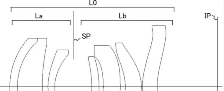
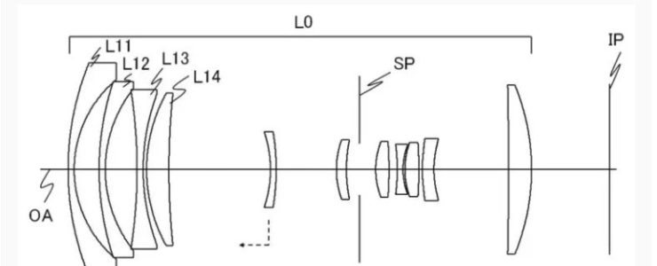
- A zoom lens is provided that has a wide angle of view, is compact, and has high optical performance while allowing rapid zooming.
- [Background Art]In recent years, there has been a demand for zoom lenses that are wide-angle, compact, and high-performance (high resolution). In addition, in recent years, the demand for moving images has increased, and in order to achieve smooth zooming, zoom lenses with electric zoom functions are required. As a wide-angle optical system, a negative lead type optical system is known. Patent Document 1 and Patent Document 2 disclose a negative lead type zoom lens in which the first lens group is immobile relative to the image plane during zooming.
- SUMMARY OF THE PRESENT EMBODIMENTS
An object of the present invention is to provide a zoom lens which has a wide angle of view, is compact, has high optical performance, and is capable of rapid zooming.
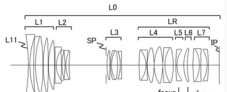
Example 1
- Focal length: 14.40-29.10
- F-number: 4.10-6.26
- Half angle of view: 43.6-25.3
- Image height: 11.51-12.90
- Overall length: 78.75
- Back Focus: 11.50
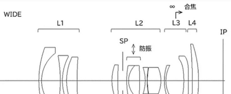
Example 2
- Focal length: 24.70-48.50
- F-number: 4.10-6.14
- Half angle of view: 41.5-24.0
- Image height: 18.19-20.62
- Overall length: 107.48
- Back Focus: 20.26
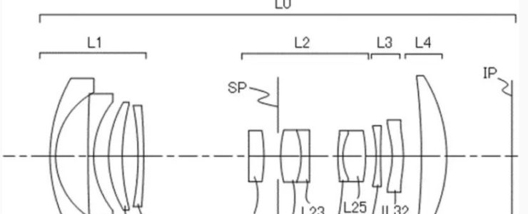
Example 3
- Focal length: 12.36-27.16
- F-number: 4.10-6.40
- Half angle of view: 47.9-26.2
- Image height: 10.67-12.59
- Overall length: 79.81
- Back Focus: 11.50