Canon has filed a patent application (publication number P2026052804, published March 25, 2026, filed September…
Canon Patent: Electric Tilt-shift Lens Operation
This is a rather interesting Canon patent application, and it might well go into production one day.
Canon patent application 2023135457 (japan, published 9/28/2023) discusses technology and methods to implement an electronic, motor-driven tilt-shift lens operation. The following excerpt from the patent literature should make this more clear:
An object of the present invention is to provide a control device that can reduce the effort and time of operation and improve the convenience of tilt photography and shift photography.
Background Art
Patent Document 1 describes tilt photography in which the in-focus range is adjusted by moving two optical element groups in a direction perpendicular to the optical axis, and tilt photography in which the shooting angle of view is changed and distortion is corrected. An optical system is disclosed that can perform shift photography.
In recent years, the number of situations in which tilt photography and shift photography are used has been increasing, and there is an urgent need to reduce the effort and time required for operations in such photography. However, in the optical system of Patent Document 1, there is no mention of reduction in operational effort and time.
An object of the present invention is to provide a control device that can reduce the effort and time of operation and improve the convenience of tilt photography and shift photography.
Means for Solving the Problems
A control device according to one aspect of the present invention includes an imaging device including an imaging device, and a tilt effect that tilts a focus plane with respect to an imaging surface of the imaging device and moves a shooting range. A control device used in a camera system having a lens device including at least one optical member for changing at least one of a shift effect and a shift effect, in which a first operation instruction based on an operation on an operation unit is acquired, A first control unit that moves at least one optical member in response to an operation, and moves the at least one optical member to a preset position when a second operation instruction different from the first operation instruction is obtained. and a second control section.
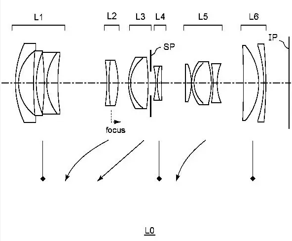
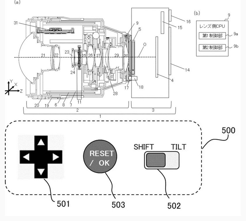
In this embodiment, by moving the sixth group lens 26 and the eighth group lens 28 in a direction perpendicular to the optical axis O, the tilt effect and shift effect can be changed. Specifically, by moving the sixth group lens 26 and the eighth group lens 28 in opposite directions, the tilt effect can be changed, and by moving them in the same direction, the shift effect can be changed. The lens-side CPU 9 controls the movement of the sixth group lens 26 via a drive section using a signal from a detection section (not shown) that detects the amount of movement of the sixth group lens 26. Further, the lens-side CPU 9 controls the movement of the 8th group lens 28 via the drive section using a signal from a detection section (not shown) that detects the amount of movement of the 8th group lens 28. The drive unit that moves the sixth group lens 26 and the eighth group lens 28 is, for example, a stepping motor or a voice coil motor (VCM). Note that it is also possible to change the tilt effect by tilting (rotating) the lens.
FIG. 3 [on top, editor’s note] is an explanatory diagram of the operation unit 500 for changing the tilt effect and shift effect. The operation unit 500 includes a direction key 501, a slide switch (selection unit) 502, and a decision/cancel button 503. The operation unit 500 is provided on the lens barrel 2 so that it can be operated by a photographer. Note that although the operating unit 500 is provided on the lens barrel 2 in this embodiment, it may also be provided on the camera 3. Further, a part of the operation unit 500 (for example, the direction key 501) may be provided on the lens barrel 2, and another part (for example, the enter/cancel button 503) may be provided on the camera 3. Further, instead of the direction key 501, an operating member such as a joystick, a lever, or an operating ring may be used. Furthermore, instead of providing the operation section 500, a screen for executing the same functions as the operation section 500 may be displayed on the display section 14, for example. Furthermore, the functions of the operation section 500 may be assigned to an existing operation member provided in the camera system 1.
More Canon patents are listed here.
[via asobinet]
Related Posts