Canon Patent: TS-R 180mm F3.5 And TS-R 100mm F2.8 Lenses

Tilt-shift

There must be a tilt-shift lens for the RF mount on Canon’s release radar, given all these pertinent patents we are seeing. I am pretty sure that soon the clickbaiters out there will break the news with rumors about…tilt-shift lenses for the RF mount.

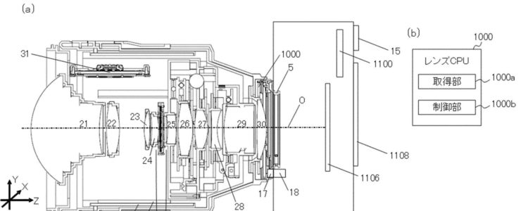
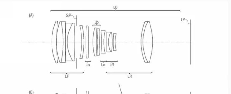
Canon patent 2023162714 (Japan, published 11/9/2023) discusses optical formulas for two tilt-shift lenses for the RF mount:

  • TS-R 180mm F3.5
  • TS-R 100mm F2.8

From the patent literature:

  • [Problem] To obtain an optical system that can greatly tilt an in-focus object surface while reducing composition shift while the entire system is small.
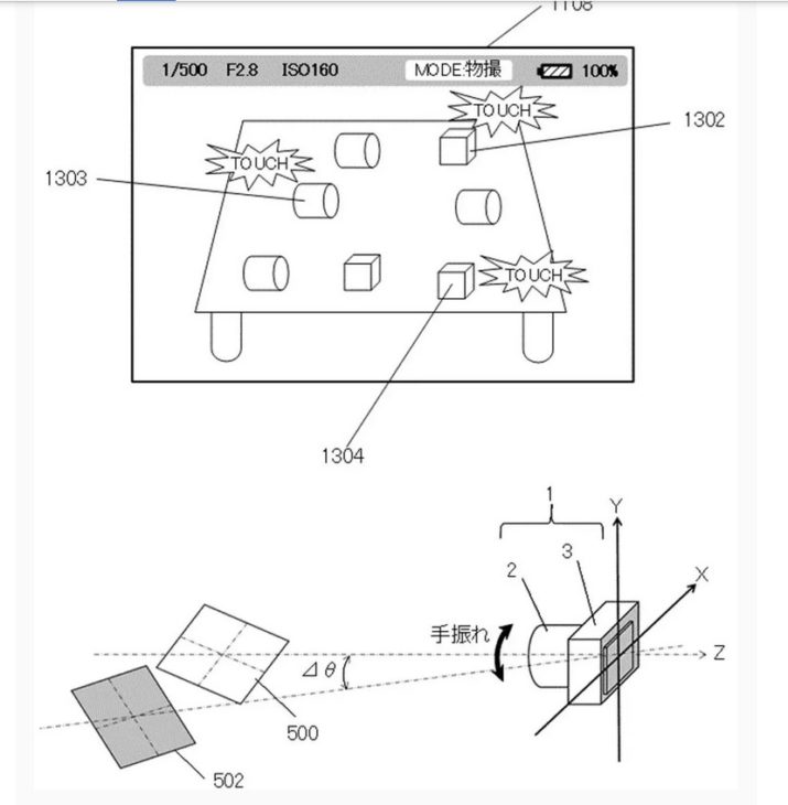
  • BACKGROUND TECHNOLOGY: Photography that focuses on an object surface that is tilted with respect to a direction perpendicular to the optical axis is called tilt photography. In tilt photography, it is necessary to greatly tilt the surface of the object in focus in order to expand the range of image expression.
  • As an optical system for realizing this photographing, an imaging optical system equipped with a tilt mechanism is known.
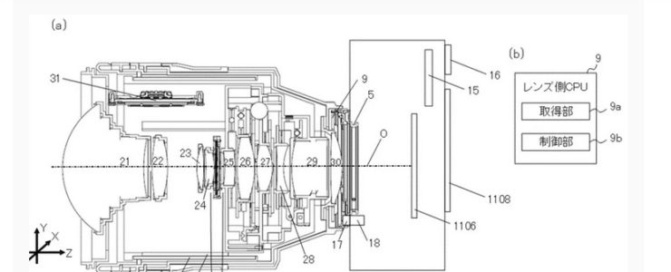
  • On the other hand, in an imaging optical system having a tilt mechanism, the composition shifts (hereinafter also referred to as “composition shift”) when the system is tilted, which may impair convenience.
  • On the other hand, an imaging optical system is known that includes a plurality of lens sections that move in a direction perpendicular to the optical axis direction (Patent Document 1). In Patent Document 1, during tilt photography, the lens section A moves in a direction perpendicular to the optical axis direction, and the lens section B moves in a direction perpendicular to the optical axis direction so as to correct the shift effect generated in the lens section A. By moving the lens in the vertical direction, it is possible to take tilted shots with small composition shifts.
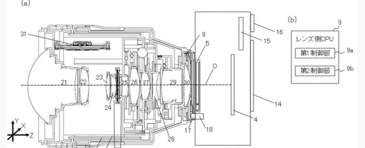
  • An imaging optical system that includes a plurality of lens units that move in a direction perpendicular to the optical axis direction as in Patent Document 1 moves the lens unit in a direction perpendicular to the optical axis direction during tilt photography. Aberrations occur due to optical eccentricity. The amount of aberration caused by this eccentricity increases as the amount of inclination of the object surface for tilt photography increases. In Patent Document 1, since the lens group A that moves in the direction perpendicular to the optical axis direction has negative refractive power, the height from the optical axis of off-axis light incident on the lens section B increases, and the lens The amount of eccentric aberration that occurs when portion B is decentered increases. Furthermore, since the height of the off-axis light from the optical axis increases, the diameter of the lens portion B increases. Therefore, it becomes difficult to increase the eccentricity of the lens portion B, and as a result, it is difficult to greatly tilt the object surface that is in focus.
  • Accordingly, an object of the present invention is to provide an optical system that can greatly tilt the object surface in focus while reducing composition shift while the entire system is small, and an imaging apparatus having the same.

Example 1

  • Focal length: 179.88
  • F value: 3.60
  • Half angle of view: 6.86
  • Image height: 21.64
  • Total length: 198.10
  • Back focus: 27.03

Example 2

  • Focal length: 193.86
  • F value: 2.88
  • Half angle of view: 6.37
  • Image height: 21.64
  • Total length: 182.73
  • Back focus: 26.48

Example 3

  • Focal length: 97.23
  • F value: 2.88
  • Half angle of view: 12.54
  • Image height: 21.64
  • Total length: 176.52
  • Back focus: 14.71

Example 4

  • Focal length: 89.85
  • F value: 3.50
  • Half angle of view: 13.54
  • Image height: 21.64
  • Total length: 184.06
  • Back focus: 28.19

Example 5

  • Focal length: 134.80
  • F value: 3.50
  • Half angle of view: 9.12
  • Image height: 21.64
  • Total length: 135.33
  • Back focus: 37.11

More Canon patents are listed here.

[via asobinet]

Canon Patent: On Camera Display Of Tilt-shift Information

Canon

Here is a new Canon patent, and it is another one referring to tilt-shift lenses.

Canon patent application 2023160385 (japan, published 11/2/2023) discusses methods and technology to display tilt-shift lens information on the camera display.

From the patent literature:

  • An object of the present invention is to provide a lens device that makes it possible to check the amount of tilting on a display screen provided in an imaging device.
  • BACKGROUND ART
    Conventionally, interchangeable lens cameras have been known that adjust the amount of tilt, such as the amount of shift and tilt amount, with respect to the imaging surface of the lens in order to perform tilted imaging. Patent Document 1 discloses a configuration in which the depth of field based on the amount of tilt is displayed on a screen provided in a camera.
  • An object of the present invention is to provide a lens device that makes it possible to check the amount of fanning on a display screen provided in an imaging device.
  • Means for Solving the Problems
    A lens device according to one aspect of the present invention is a lens device that can be attached to an imaging device, and includes at least one optical member that is moved to perform tilted imaging. It is characterized by having an imaging optical system and a transmitter that transmits information regarding the movable range of at least one optical member to the imaging device.
  • Effects of the Invention
    According to the present invention, it is possible to provide a lens device that allows the amount of tilting to be confirmed on a display screen provided in an imaging device.
  • The zoom lens 102 is movable along the optical axis of the imaging optical system, which is indicated by a broken line in the figure. When the user operates a zoom operation ring connected to a zoom mechanism (not shown), the zoom lens 102 moves along the optical axis. Thereby, zooming is performed in which the focal length of the photographing optical system is changed by moving the zoom lens 102. The zoom lens position detection unit 106 detects the position of the zoom lens 102 using a position detection sensor such as a variable resistor, and outputs position data to the lens microcomputer 111. The output position data is used by the lens microcomputer 111 to control zoom tracking operations and the like.
  • The aperture unit 103 includes sensors such as aperture blades and a Hall element. The state of the aperture blades is detected by the aforementioned sensor and output to the lens microcomputer 111. The aperture control unit 107 drives actuators such as a stepping motor and a voice coil motor in accordance with commands from the lens microcomputer 111. This allows the aperture unit 103 to adjust the amount of light.
  • The image blur correction lens 104 reduces image blur caused by hand shake and the like by moving in a direction perpendicular to the optical axis of the imaging optical system. The image shake correction lens control unit 108 drives the shake prevention actuator in response to a shake detected by a shake sensor (not shown) such as a vibration gyro based on a command from the lens microcomputer 111. As a result, image stabilization processing for controlling the shift operation of the image shake correction lens 104 is performed.
  • The focus lens 105 is movable along the optical axis. Position data of the focus lens 105 detected using a position detection sensor such as a photo interrupter is output to the lens microcomputer 111. The focus lens control unit 109 adjusts the focus by driving an actuator such as a stepping motor and moving the focus lens 105 based on a command from the lens microcomputer 111. Further, the focus lens 105 corrects image plane fluctuations caused by zooming by the zoom lens 102.
  • The revolving drive unit (rotating member) 114 is configured to be rotatable around the optical axis of the imaging optical system, and rotates at least a portion of the imaging optical system around the optical axis by rotating. The revolving control unit 117 moves the revolving drive unit 114 according to a command from the lens microcomputer 111. The position of the revolving drive unit 114 may be detected by a position detection unit (not shown). By executing a revolving drive that moves the revolving drive unit 114, the moving directions of the tilt lens 112 and the shift lens 113 can be controlled.

More Canon patents are listed here.

Canon Patent: Keep High-precision Autofocus During Tilt-shift Operations

Canon Patent

Here is a new Canon patent application, another one that deals with tilt-shift lenses.

The Canon patent application, published on October 18, 2023, discusses methods and technology to make sure autofocus is kept during tilt-shift operations with the lens.

From the patent literature:

  • An object of the present invention is to provide a control device that can maintain focus with high accuracy even when obtaining a tilt effect or a shift effect.
  • Background Art
    Conventionally, a tilt effect that tilts the focusing surface and a shift effect that moves the shooting range have been used to achieve good overall focus on an object surface that is tilted with respect to the optical axis of an imaging optical system. A resulting optical system has been proposed. Patent Document 1 discloses an optical system that can obtain a tilt effect and a shift effect by moving two optical elements in a direction perpendicular to the optical axis.
  • However, the optical system of Patent Document 1 does not take into account that the amount of defocus changes by moving the optical element in the direction perpendicular to the optical axis, so it does not take into account that the tilt effect or shift effect is applied after focusing. If the optical element is moved in a direction perpendicular to the optical axis in order to obtain an image, the focus will shift.
  • An object of the present invention is to provide a control device that can maintain focus with high precision even when obtaining a tilt effect or a shift effect.

More Canon patents are listed here.

[via asobinet.com]

Canon Patent: Electric Tilt-shift Lens Operation (take #2)

Canon Patent

Here is another Canon patent for electric tilt-shift lens operation. The other one was published last week.

Canon patent application 2023-140195A (Japan, published 10/4/2023) discusses technology and methods for a tilt-shift lens with electronic controls.

From the patent literature:

An object of the present invention is to provide a control device that can establish a desired focus plane for a desired subject or object plane using a desired tilt effect in hand-held photography.

BACKGROUND ART

Conventionally, an optical system has been proposed that has a tilt effect that tilts a focusing surface so that an object surface tilted with respect to the optical axis of an imaging optical system is brought into good focus over the entire surface. . Patent Document 1 discloses a surveillance camera system that includes a lens unit and a camera device that have a tilt effect, determines the amount of tilt for each specific area set as a shooting range, and focuses on a subject using a desired focus plane.

However , in the camera system disclosed in Patent Document 1, when the position of the camera device changes, it is necessary to set the tilt amount for each specific area. Therefore, when hand-held photography is performed using the camera system of Patent Document 1, there is a possibility that the desired tilt effect may not be obtained.

SUMMARY OF THE INVENTION

An object of the present invention is to provide a control device that can establish a desired focus plane for a desired subject or object plane using a desired tilt effect during hand-held photography .

Means for Solving the Problems

A control device as one aspect of the present invention includes an imaging device including an imaging device, and at least one optical member for tilting a focusing surface with respect to an imaging surface of the imaging device. A control device used in a camera system having a lens device having an optical system including an acquisition unit that acquires information about a designated subject, and a subject for constructing a focus plane based on information about the designated subject. and a control unit that acquires information regarding the position of the.

The lens barrel 2 has an optical system, a zoom operation ring 6, a guide barrel 7, a cam barrel 8, a lens-side CPU 9, and an aperture mechanism 11 . The optical system includes a first group lens 21, a second group lens 22, a third group lens 23, a fourth group lens 24, a fifth group lens 25, a sixth group lens 26, a seventh group lens 27, an eighth group lens 28, a ninth group lens 29, and A 10-group lens 30 is provided. In this embodiment, by moving at least one lens (optical member) included in the optical system, at least a tilt effect that tilts the focus plane with respect to the imaging surface of the image sensor 1106 and a shift effect that moves the imaging range are achieved. You can get one. Each lens is held by a lens barrel with a cam follower. The cam follower engages with a straight groove parallel to the optical axis O provided on the guide tube 7 and a cam groove inclined with respect to the optical axis O provided on the cam tube 8. When the zoom operation ring 6 rotates, the cam cylinder 8 rotates, and the positional relationship of each lens in the Z-axis direction changes. As a result, the focal length of the lens barrel 2 changes. The focal length of the lens barrel 2 can be detected by a zoom position detection section (not shown) that detects the amount of rotation of the zoom operation ring 6. The lens-side CPU 009 changes the aperture diameter of the optical system by controlling the aperture mechanism 11. In this embodiment, by moving the sixth group lens 26 and the eighth group lens 28 in a direction perpendicular to the optical axis O, a tilt effect or a shift effect can be obtained. Specifically, by moving the sixth group lens 26 and the eighth group lens 28 in opposite directions, a tilt effect can be obtained, and by moving them in the same direction, a shift effect can be obtained. The lens-side CPU 9 controls the sixth lens group 26 via a drive section using a signal from a detection section (not shown) that detects the amount of movement of the sixth lens group 26 . Further, the lens side CPU 9 controls the 8th group lens 28 via a drive section using a signal from a detection section (not shown) that detects the amount of movement of the 8th group lens 28. The drive unit that moves the sixth group lens 26 and the eighth group lens 28 is, for example, a stepping motor or a voice coil motor (VCM). Note that it is also possible to obtain a tilt effect by tilting (rotating) the lens.

In the camera system 1 of this embodiment, if three points to be focused are specified, the subject plane 500 is constructed as described above, and photography can be performed with the desired subject in focus . However, for example, in so-called “reverse tilt photography (miniature photography)” in which cityscapes and people are photographed by blurring the top and bottom of the photograph, the photographer may decide where to focus and what to blur. In that case, the vector OB is defined by the spatial coordinate points O and B designated by the photographer. The photographer instructs the surface 501 to rotate by an angle θctrl using the vector OB as the rotation axis. For example, the photographer can instruct the surface 501 to rotate by an angle θctrl by performing a touch operation of sliding a finger back and forth on the display unit 1108. Further, instructions may be given using line-of-sight input using the EVF, rotating operation of the aperture operation ring 20, and buttons or dials (not shown). Alternatively, it may be determined automatically according to the set shooting mode of the camera 3. The photographer aligns the object surface 500 with the surface 501 that provides the desired degree of blur while maintaining the desired object (spatial coordinate points O, B) in focus.

More Canon patents are listed here.

[via asobinet]

Canon Patent: Electric Tilt-shift Lens Operation

Canon Patent

This is a rather interesting Canon patent application, and it might well go into production one day.

Canon patent application 2023135457 (japan, published 9/28/2023) discusses technology and methods to implement an electronic, motor-driven tilt-shift lens operation. The following excerpt from the patent literature should make this more clear:

An object of the present invention is to provide a control device that can reduce the effort and time of operation and improve the convenience of tilt photography and shift photography.

Background Art

Patent Document 1 describes tilt photography in which the in-focus range is adjusted by moving two optical element groups in a direction perpendicular to the optical axis, and tilt photography in which the shooting angle of view is changed and distortion is corrected. An optical system is disclosed that can perform shift photography.

In recent years, the number of situations in which tilt photography and shift photography are used has been increasing, and there is an urgent need to reduce the effort and time required for operations in such photography. However, in the optical system of Patent Document 1, there is no mention of reduction in operational effort and time.

An object of the present invention is to provide a control device that can reduce the effort and time of operation and improve the convenience of tilt photography and shift photography.

Means for Solving the Problems

A control device according to one aspect of the present invention includes an imaging device including an imaging device, and a tilt effect that tilts a focus plane with respect to an imaging surface of the imaging device and moves a shooting range. A control device used in a camera system having a lens device including at least one optical member for changing at least one of a shift effect and a shift effect, in which a first operation instruction based on an operation on an operation unit is acquired, A first control unit that moves at least one optical member in response to an operation, and moves the at least one optical member to a preset position when a second operation instruction different from the first operation instruction is obtained. and a second control section.

In this embodiment, by moving the sixth group lens 26 and the eighth group lens 28 in a direction perpendicular to the optical axis O, the tilt effect and shift effect can be changed. Specifically, by moving the sixth group lens 26 and the eighth group lens 28 in opposite directions, the tilt effect can be changed, and by moving them in the same direction, the shift effect can be changed. The lens-side CPU 9 controls the movement of the sixth group lens 26 via a drive section using a signal from a detection section (not shown) that detects the amount of movement of the sixth group lens 26. Further, the lens-side CPU 9 controls the movement of the 8th group lens 28 via the drive section using a signal from a detection section (not shown) that detects the amount of movement of the 8th group lens 28. The drive unit that moves the sixth group lens 26 and the eighth group lens 28 is, for example, a stepping motor or a voice coil motor (VCM). Note that it is also possible to change the tilt effect by tilting (rotating) the lens.

FIG. 3 [on top, editor’s note] is an explanatory diagram of the operation unit 500 for changing the tilt effect and shift effect. The operation unit 500 includes a direction key 501, a slide switch (selection unit) 502, and a decision/cancel button 503. The operation unit 500 is provided on the lens barrel 2 so that it can be operated by a photographer. Note that although the operating unit 500 is provided on the lens barrel 2 in this embodiment, it may also be provided on the camera 3. Further, a part of the operation unit 500 (for example, the direction key 501) may be provided on the lens barrel 2, and another part (for example, the enter/cancel button 503) may be provided on the camera 3. Further, instead of the direction key 501, an operating member such as a joystick, a lever, or an operating ring may be used. Furthermore, instead of providing the operation section 500, a screen for executing the same functions as the operation section 500 may be displayed on the display section 14, for example. Furthermore, the functions of the operation section 500 may be assigned to an existing operation member provided in the camera system 1.

More Canon patents are listed here.

[via asobinet]

Is Canon Testing Prototypes Of Upcoming Tilt-shift Lenses?

TS-E 17mm F/4L

It seems Canon might be set to soon announce new tilt-shift lenses for the RF mount.

Rumor has it that Canon is already testing two tilt-shift lenses in the wild. The source claims they have been “told that the new tilt-shift lenses are in the hands of a select group of photographers“. These are the two rumored tilt-shift lenses:

  • Canon TS-R 14mm f/4L
  • Canon TS-R 24mm f/3.5L

What do you think?

Source: Canon Rumors