Canon has filed a patent application (publication number P2026052804, published March 25, 2026, filed September…
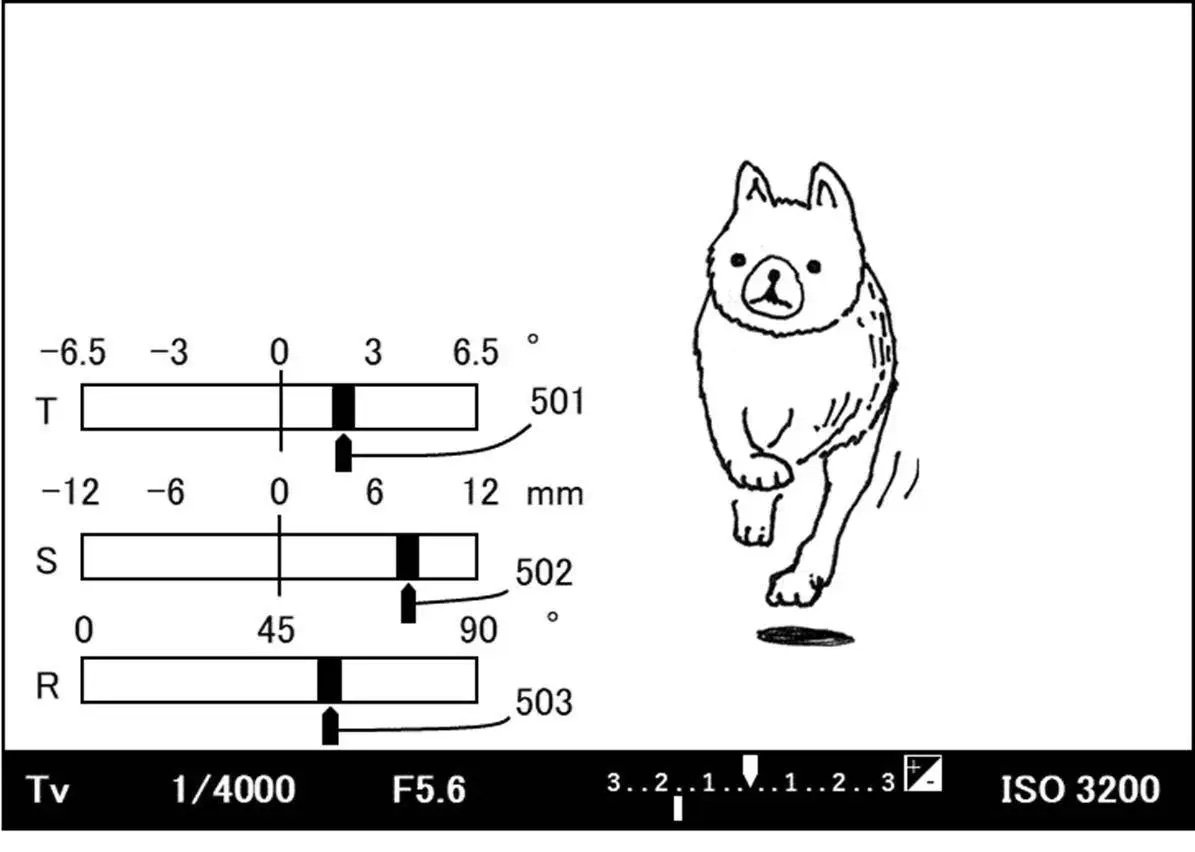
Canon Patent: On Camera Display Of Tilt-shift Information
Here is a new Canon patent, and it is another one referring to tilt-shift lenses.
Canon patent application 2023160385 (japan, published 11/2/2023) discusses methods and technology to display tilt-shift lens information on the camera display.
From the patent literature:
- An object of the present invention is to provide a lens device that makes it possible to check the amount of tilting on a display screen provided in an imaging device.
- BACKGROUND ART
Conventionally, interchangeable lens cameras have been known that adjust the amount of tilt, such as the amount of shift and tilt amount, with respect to the imaging surface of the lens in order to perform tilted imaging. Patent Document 1 discloses a configuration in which the depth of field based on the amount of tilt is displayed on a screen provided in a camera. - An object of the present invention is to provide a lens device that makes it possible to check the amount of fanning on a display screen provided in an imaging device.
- Means for Solving the Problems
A lens device according to one aspect of the present invention is a lens device that can be attached to an imaging device, and includes at least one optical member that is moved to perform tilted imaging. It is characterized by having an imaging optical system and a transmitter that transmits information regarding the movable range of at least one optical member to the imaging device. - Effects of the Invention
According to the present invention, it is possible to provide a lens device that allows the amount of tilting to be confirmed on a display screen provided in an imaging device. - The zoom lens 102 is movable along the optical axis of the imaging optical system, which is indicated by a broken line in the figure. When the user operates a zoom operation ring connected to a zoom mechanism (not shown), the zoom lens 102 moves along the optical axis. Thereby, zooming is performed in which the focal length of the photographing optical system is changed by moving the zoom lens 102. The zoom lens position detection unit 106 detects the position of the zoom lens 102 using a position detection sensor such as a variable resistor, and outputs position data to the lens microcomputer 111. The output position data is used by the lens microcomputer 111 to control zoom tracking operations and the like.
- The aperture unit 103 includes sensors such as aperture blades and a Hall element. The state of the aperture blades is detected by the aforementioned sensor and output to the lens microcomputer 111. The aperture control unit 107 drives actuators such as a stepping motor and a voice coil motor in accordance with commands from the lens microcomputer 111. This allows the aperture unit 103 to adjust the amount of light.
- The image blur correction lens 104 reduces image blur caused by hand shake and the like by moving in a direction perpendicular to the optical axis of the imaging optical system. The image shake correction lens control unit 108 drives the shake prevention actuator in response to a shake detected by a shake sensor (not shown) such as a vibration gyro based on a command from the lens microcomputer 111. As a result, image stabilization processing for controlling the shift operation of the image shake correction lens 104 is performed.
- The focus lens 105 is movable along the optical axis. Position data of the focus lens 105 detected using a position detection sensor such as a photo interrupter is output to the lens microcomputer 111. The focus lens control unit 109 adjusts the focus by driving an actuator such as a stepping motor and moving the focus lens 105 based on a command from the lens microcomputer 111. Further, the focus lens 105 corrects image plane fluctuations caused by zooming by the zoom lens 102.
- The revolving drive unit (rotating member) 114 is configured to be rotatable around the optical axis of the imaging optical system, and rotates at least a portion of the imaging optical system around the optical axis by rotating. The revolving control unit 117 moves the revolving drive unit 114 according to a command from the lens microcomputer 111. The position of the revolving drive unit 114 may be detected by a position detection unit (not shown). By executing a revolving drive that moves the revolving drive unit 114, the moving directions of the tilt lens 112 and the shift lens 113 can be controlled.
Related Posts