Here is another Canon patent application.
Canon patent application 2024100498 (Japan, published 7/26/2024) discusses optical formulas or three wide angle lenses:
- 9-18mm F4 IS
- 10-20mm F2.8-4 IS
- 11-22mm F2.8 IS
From the patent literature:
- A zoom lens that is compact yet has good optical performance even when vibration is reduced is provided.
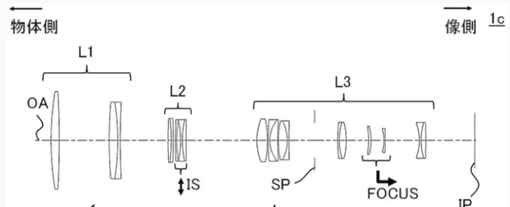
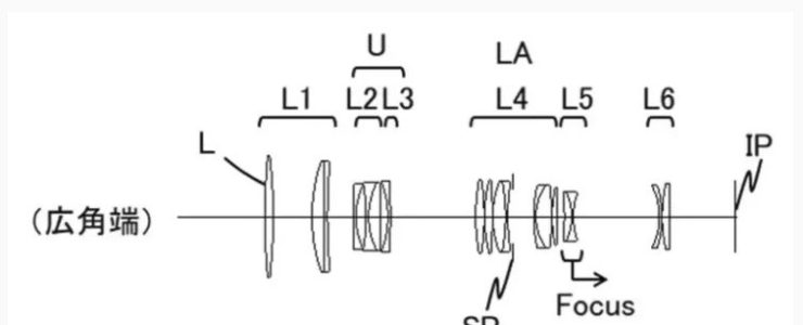
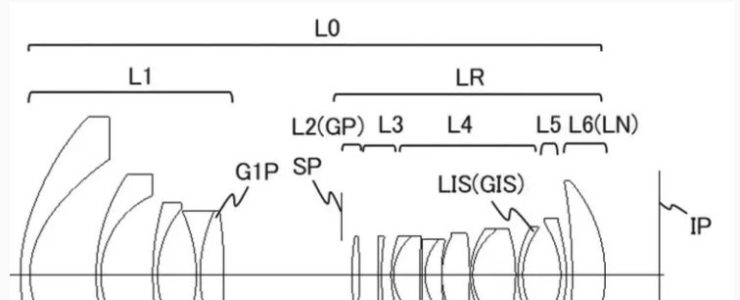
- [Background Art]As an imaging optical system used in imaging devices such as digital still cameras, video cameras, broadcast cameras, and security cameras, there is a demand for an optical system that is small and lightweight and has high optical performance even if the amount of image blur correction is large. Patent Document 1 discloses a zoom lens having a subsequent lens group including a first lens group with negative refractive power, a second lens group with positive refractive power, and an anti-vibration lens group, which are arranged in order from the object side to the image side. The anti-vibration lens group performs OIS, which reduces (corrects) image blur caused by shaking of the imaging device due to hand shake or the like (hereinafter referred to as camera shake) by moving (shifting) in a direction perpendicular to the optical axis. In addition, the imaging element that captures the subject image formed by the imaging optical system can perform IIS, which corrects image blur by shifting in a direction perpendicular to the optical axis.
- In a central projection type imaging optical system, the amount of movement of an image point on an image plane due to camera shake differs between the center and the periphery of the image plane. In particular, the wider the angle of an imaging optical system, the greater the amount of movement of an image point in the periphery compared to the center. For this reason, in an ultra-wide-angle zoom lens with an angle of view exceeding 100°, a lot of image shake remains in the periphery.
- In the zoom lens of Patent Document 1, the curvature of field during vibration reduction is corrected, but a large amount of residual image blur occurs in the peripheral area due to the difference in the amount of image point movement between the center and the periphery. Also, in the IIS, if the outer diameter of the vibration reduction lens group is large, it becomes difficult to miniaturize the zoom lens.
- The present invention provides a zoom lens which is small in size and yet has good optical performance even during vibration reduction, and an imaging apparatus using the same.
Example 1
- Focal length: 10.33-19.39
- F-number: 4.08-4.12
- Half angle of view: 61.36-48.13
- Image height: 18.92-21.64
- Total length: 128.82-123.27
- Back Focus: 12.13
Example 2
- Focal length: 9.20-17.90
- F-number: 4.08-4.12
- Half angle of view: 64.04-50.40
- Image height: 18.90-21.64
- Overall length: 125.26-119.35
- Back Focus: 10.50
Example 3
- Focal length: 11.30-23.90
- F-number: 4.08-4.12
- Half angle of view: 59.29-42.15
- Image height: 19.02-21.64
- Total length: 129.79-129.33
- Back focus: 14.54-10.54
Example 4
- Focal length: 11.30-22.00
- F-number: 2.89
- Half angle of view: 59.44-44.52
- Image height: 19.14-21.64
- Overall length: 137.35-125.58
- Back focus: 13.50-10.50
Example 5
- Focal length: 10.30-19.80
- F-number: 2.89-4.12
- Half angle of view: 61.76-47.54
- Image height: 19.18-21.64
- Overall length: 132.94-127.01
- Back Focus: 11.35