Here is a new Canon patent application, as usual for RF-mount lenses.
Canon patent application 2024042622 (japan, published 3/28/2024) discusses optical formulas for two lenses for full frame mirrorless cameras (i.e. fort he RF-mount):
- 12-24mm f/2.8
- 14-20mm f/2
From the patent literature:
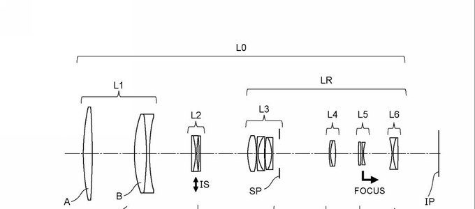
- An object of the present invention is to provide an ultra-wide-angle zoom lens that is compact and provides high optical performance over the entire object distance range.
- [ Background Art] As an imaging optical system, an imaging lens with a half angle of view of more than 50 degrees at the wide-angle end is called an ultra-wide-angle lens, and among them, a bright lens with an F value of 2.8 or less has a wide Suitable for taking advantage of the angle of view and short shutter speed for shooting starry skies and dark places. Such an ultra-wide-angle lens is required to have high resolution performance that suppresses spherical aberration and sagittal flare over a short distance from an infinite subject. Particularly in zoom lenses, there has been a problem in that it is difficult to reduce the size of the lens while suppressing variations in aberrations from the wide-angle end to the telephoto end.
- However, the zoom lens disclosed in Patent Document 1 has a large F value and cannot sufficiently reduce aberration fluctuations during zooming due to an increase in aperture. The zoom lens of Patent Document 2 reduces aberration fluctuations during zooming by having multiple groups compared to the zoom lens of Patent Document 1, but there is a need for a wider angle and a smaller size.
- An object of the present invention is to provide an ultra-wide-angle zoom lens that is compact and provides high optical performance over the entire object distance.
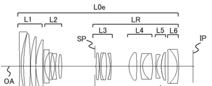
Example 1
- Focal length: 12.29-23.80
- F value: 2.93
- Half angle of view: 60.39-42.27
- Image height: 21.64
- Total length: 138.05-134.83
- Back focus: 13.86-19.48
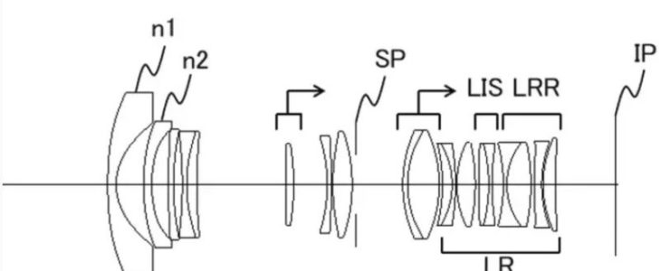
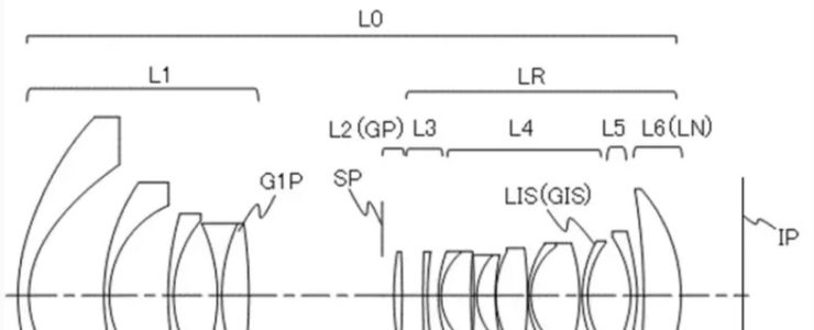
Example 2
- Focal length: 14.30-21.50
- F value: 2.06
- Half angle of view: 56.54-45.18
- Image height: 21.64
- Total length: 148.04-139.46
- Back focus: 13.87-20.30
More Canon patents are listed here.
[via asobinet]