Canon Patent: 50mm f/4 IS Macro And 90mm f/4 IS Macro
Canon patent application 2024010559 (Japan, published 01/24/2024) discusses optical formulas for two macro lenses for the RF mount:
- 50mm f/4 IS Macro
- 90mm f/4 IS Macro
From the patent literature:
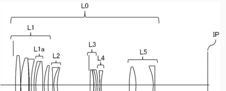
- An object of the present invention is to provide a compact and high-performance optical system in a macro lens, in which a focus lens group is made lighter and smaller, achieving higher focus stop precision and faster focusing speed.
- BACKGROUND ART
A macro lens is known as a lens capable of close-up photography. In recent years, there has been a demand for a macro lens that has high optical performance with little aberration variation in the entire focus region. - Patent Documents 1 and 2 disclose macro lenses that correct aberration fluctuations during focusing by moving a large focus lens group during focusing.
- However, in the macro lenses described in Patent Documents 1 and 2, the actuator becomes large in order to move a large focus lens group, and the focus lens group becomes large, resulting in a decrease in focus stop accuracy and focus speed. There was a problem.
- The present invention provides a compact and high-performance optical system in a macro lens by reducing the weight and size of the focus lens group, achieving high focus stop precision and high speed focusing speed.
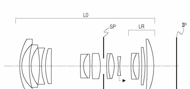
Example 1
- Focal length: 111.29
- F value: 4.12
- Half angle of view: 11.00
- Image height: 21.64
- Total length: 125.00
- Back focus: 34.03
- Magnification: 1.0
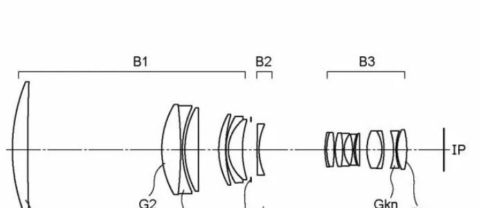
Example 2
- Focal length: 90.00
- F value: 4.12
- Half angle of view: 13.52
- Image height: 21.64
- Total length: 120.00
- Back focus: 21.58
- Magnification: 1.0
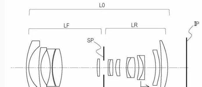
Example 3
- Focal length: 110.00
- F value: 4.12
- Half angle of view: 11.13
- Image height: 21.64
- Total length: 119.99
- Back focus: 43.07
- Magnification: 0.5
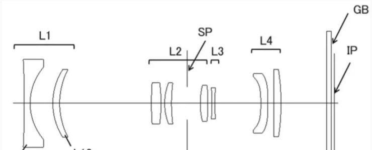
Example 4
- Focal length: 52.00
- F value: 4.12
- Half angle of view: 22.59
- Image height: 21.64
- Total length: 115.00
- Back focus: 24.18
- Magnification: 1.0