Canon Patent: Electric Tilt-shift Lens Operation

Canon Patent

This is a rather interesting Canon patent application, and it might well go into production one day.

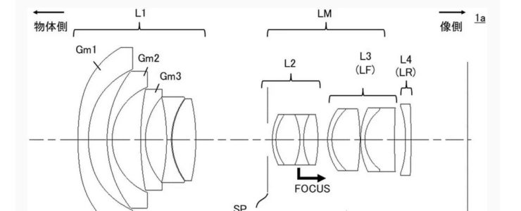
Canon patent application 2023135457 (japan, published 9/28/2023) discusses technology and methods to implement an electronic, motor-driven tilt-shift lens operation. The following excerpt from the patent literature should make this more clear:

An object of the present invention is to provide a control device that can reduce the effort and time of operation and improve the convenience of tilt photography and shift photography.

Background Art

Patent Document 1 describes tilt photography in which the in-focus range is adjusted by moving two optical element groups in a direction perpendicular to the optical axis, and tilt photography in which the shooting angle of view is changed and distortion is corrected. An optical system is disclosed that can perform shift photography.

In recent years, the number of situations in which tilt photography and shift photography are used has been increasing, and there is an urgent need to reduce the effort and time required for operations in such photography. However, in the optical system of Patent Document 1, there is no mention of reduction in operational effort and time.

An object of the present invention is to provide a control device that can reduce the effort and time of operation and improve the convenience of tilt photography and shift photography.

Means for Solving the Problems

A control device according to one aspect of the present invention includes an imaging device including an imaging device, and a tilt effect that tilts a focus plane with respect to an imaging surface of the imaging device and moves a shooting range. A control device used in a camera system having a lens device including at least one optical member for changing at least one of a shift effect and a shift effect, in which a first operation instruction based on an operation on an operation unit is acquired, A first control unit that moves at least one optical member in response to an operation, and moves the at least one optical member to a preset position when a second operation instruction different from the first operation instruction is obtained. and a second control section.

In this embodiment, by moving the sixth group lens 26 and the eighth group lens 28 in a direction perpendicular to the optical axis O, the tilt effect and shift effect can be changed. Specifically, by moving the sixth group lens 26 and the eighth group lens 28 in opposite directions, the tilt effect can be changed, and by moving them in the same direction, the shift effect can be changed. The lens-side CPU 9 controls the movement of the sixth group lens 26 via a drive section using a signal from a detection section (not shown) that detects the amount of movement of the sixth group lens 26. Further, the lens-side CPU 9 controls the movement of the 8th group lens 28 via the drive section using a signal from a detection section (not shown) that detects the amount of movement of the 8th group lens 28. The drive unit that moves the sixth group lens 26 and the eighth group lens 28 is, for example, a stepping motor or a voice coil motor (VCM). Note that it is also possible to change the tilt effect by tilting (rotating) the lens.

FIG. 3 [on top, editor’s note] is an explanatory diagram of the operation unit 500 for changing the tilt effect and shift effect. The operation unit 500 includes a direction key 501, a slide switch (selection unit) 502, and a decision/cancel button 503. The operation unit 500 is provided on the lens barrel 2 so that it can be operated by a photographer. Note that although the operating unit 500 is provided on the lens barrel 2 in this embodiment, it may also be provided on the camera 3. Further, a part of the operation unit 500 (for example, the direction key 501) may be provided on the lens barrel 2, and another part (for example, the enter/cancel button 503) may be provided on the camera 3. Further, instead of the direction key 501, an operating member such as a joystick, a lever, or an operating ring may be used. Furthermore, instead of providing the operation section 500, a screen for executing the same functions as the operation section 500 may be displayed on the display section 14, for example. Furthermore, the functions of the operation section 500 may be assigned to an existing operation member provided in the camera system 1.

More Canon patents are listed here.

[via asobinet]

Canon Patent: 200-1000mm F5.6-11 IS And 200-800mm F5.6-8 IS Lenses

Canon Patent

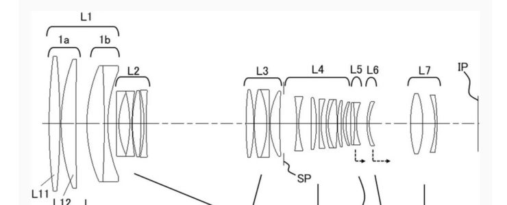
Here is a new Canon patent application: two super telephoto zooms for the RF mount.

Canon patent application 2023135180 (Japan, published 9/28/2023) discusses optical formulas for two super telephoto zoom lenses for the RF mount:

  • 200-1000mm F5.6-11 IS
  • 200-800mm F5.6-8 IS

From the patent literature:

To obtain a zoom lens whose entire system is compact and whose optical performance is suppressed from deteriorating due to focusing.

BACKGROUND ART

As an imaging optical system, a telephoto zoom lens having a long focal length at the telephoto end is known. (Patent Document 1) Such a zoom lens is required to be small, yet easy to perform high-speed focusing, and to suppress deterioration of optical performance due to focusing.

However, the zoom lens disclosed in Patent Document 1 has a large number of lenses in the fourth lens group, which is a focus group, and also has relatively strong refractive power. Therefore, it is difficult to simultaneously increase the speed of focusing and suppress deterioration in optical performance due to focusing.

SUMMARY OF THE INVENTION

Therefore, an object of the present invention is to provide a zoom lens whose entire system is small in size and whose optical performance is suppressed from deteriorating due to focusing, and an imaging device having the zoom lens.

Example 1

  • Focal length: 206.00-778.20
  • F value: 5.71-9.18
  • Half angle of view: 6.00-1.59
  • Image height: 21.64
  • Total length: 330.11-420.11
  • Back focus: 40.03-96.02

Example 2

  • Focal length: 200.00-998.33
  • F value: 5.71-11.00
  • Half angle of view: 6.17-1.24
  • Image height: 21.64
  • Total length: 346.80-456.78
  • Back focus: 43.85-105.49

Example 3

  • Focal length: 206.00-775.95
  • F value: 5.83-8.00
  • Half angle of view: 6.00-1.60
  • Image height: 21.64
  • Total length: 330.08-420.12
  • Back focus: 38.46-38.46

More Canon patents are listed here.

[via asobinet]
Canon Patent: 11mm F2, 13mm F2, 22mm F2, And 30mm F2 Lenses For RF-S Mount

Canon Patent

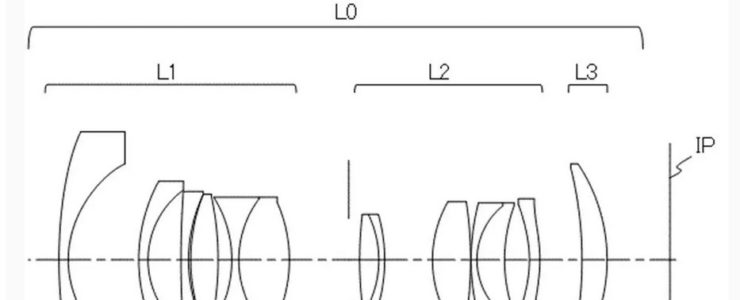
Here is a new Canon patent application, for a bunch of fast primes for the RF-S mount.

Canon patent application P2023130885 (Japan, published 9/21/2023) discusses optical formulas for RF-S mount prime lenses:

  • 11mm F2
  • 13mm F2
  • 22mm F2
  • 30mm F2

From the patent literature:

An object of the present invention is to provide a rear focus optical system that is compact and capable of good aberration correction.

BACKGROUND ART

In imaging, it is required to suppress the generation of noise during zooming and focusing. In order to suppress noise during focusing, the rear focus (inner focus) method, in which focusing is performed by moving the lens group closest to the image side than the lens group closest to the object side, is recommended because it provides the best sound isolation effect from the object side lens. suitable.

Rear focus type optical systems are also required to be compact and have good aberration correction. In order to realize such an optical system, it is necessary to appropriately set the lens arrangement and the focal length of each lens.

The present invention provides a rear focus type optical system that is compact and capable of good aberration correction, and an imaging device equipped with the same.

Example 1

  • Focal length: 13.40
  • F value: 2.06
  • Half angle of view: 43.01
  • Image height: 12.50
  • Total length: 77.83
  • Back focus: 12.43

Example 2

  • Focal length: 11.30
  • F value: 2.06
  • Half angle of view: 47.89
  • Image height: 12.50
  • Total length: 77.85
  • Back focus: 12.44

Example 3

  • Focal length: 22.00
  • F value: 2.06
  • Half angle of view: 29.60
  • Image height: 12.50
  • Total length: 72.85
  • Back focus: 12.444

Example 4

  • Focal length: 30.52
  • F value: 2.06
  • Half angle of view: 22.27
  • Image height: 12.50
  • Total length: 75.88
  • Back focus: 14.49

More Canon patents are listed here.

[via asobinet]
Canon patent: 55mm F1.24 Lens With Double Gauss Element Arrangement

Canon Patent

Another Canon patent, although we doubt that this one will ever hit the market.

Canon patent application 2023127280 (Japan, published 9/13/2023) discusses optical formulas for a 55mm F1.24 lens with a double Gauss element arrangement.

From the patent literature:

An object of the present invention is to provide an optical system that has a bright F number, is compact, has high optical performance, and also suppresses fluctuations in various aberrations associated with focusing.

Background Art

In recent years, photographing optical systems with a standard angle of view, where the half angle of view is about 20 degrees to 30 degrees, used in imaging devices have a bright F number and have high optical performance despite the small size of the entire system. That is required. A so-called double Gauss type optical system is known as a standard angle of view photographing optical system. In a Gauss type optical system, the lenses are arranged symmetrically around the aperture, and with a small number of lenses, it is possible to obtain high optical performance despite being compact.

However, in the optical system described in Patent Document 1, the back focus tends to become long and the total length of the lens becomes long, so it is difficult to suppress the increase in size of the imaging device.

In order to achieve a compact lens with a high F-number, high optical performance, and suppression of fluctuations in various aberrations associated with focusing, it is important to appropriately set the structure and material of the lens.

An object of the present invention is to provide an optical system that has a bright F number, is compact, has high optical performance, and also suppresses fluctuations in various aberrations associated with focusing.

Example 1

  • Focal length: 53.80
  • F value: 1.24
  • Half angle of view: 21.91
  • Image height: 21.64
  • Total length: 78.46
  • Back focus: 29.83

Example 2

  • Focal length: 55.98
  • F value: 1.24
  • Half angle of view: 21.13
  • Image height: 21.64
  • Total length: 84.99
  • Back focus: 30.07

Example 3

  • Focal length: 56.00
  • F value: 1.24
  • Half angle of view: 21.12
  • Image height: 21.64
  • Total length: 79.92
  • Back focus: 30.00

More Canon patents are listed here.

[via asobinet]
Canon Patent: In Camera Built-in Neutral Density Filter

Canon Patent

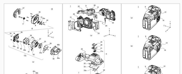
That’s an interesting Canon patent that was spotted in japan: a built-in ND (Neutral density) filter.

Canon patent application 2023128236 (Japan, published 9/14/2023) discusses methods and technology for an ND filter that is built-in on the camera body.

Excerpts from the patent literature:

An object of the present invention is to provide an imaging device in which an optical filter can be easily switched between a used state and a non-used state, and can appropriately control foreign matter removal from the surface of an imaging unit.

BACKGROUND ART

Conventionally, imaging devices capable of capturing images using optical filters such as neutral density filters (ND filters) have been known. Patent Document 1 discloses an imaging device that includes a plurality of ND filters and can move up and down. Patent Document 2 discloses a configuration including a through hole for blowing gas to blow away dust attached to the ND filter.

In the configuration disclosed in Patent Document 1, it is difficult to hermetically seal the ND filter and the imaging device, so there is a possibility that dust and the like may enter the interior of the imaging device. Although the configuration disclosed in Patent Document 2 can remove dust etc. attached to the ND filter, it is not possible to properly control the function of removing dust etc. attached to the surface of the image sensor unit, so that the captured image may not be affected. Dust, etc. may be reflected.

Therefore, it is an object of the present invention to provide an imaging device in which it is possible to easily switch between a state in which an optical filter is used and a state in which it is not in use, and in which foreign matter removal from the surface of an imaging unit can be properly controlled. purpose.

Effects of the Invention

According to the present invention, an image pickup device in which it is possible to easily switch between the use state and the non-use state of the optical filter, and it is possible to properly control foreign matter removal from the surface of the imaging unit. equipment can be provided.

More Canon patents are listed here.

[via asobinet]
Canon Patent: 200-800mm F5.6-9, 100-600mm F5.6-9 And 20-150mm F4-8

Canon Patent

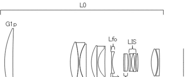
A new Canon patent was spotted. Zoom lenses for full frame mirrorless cameras, i.e. the EOS R system.

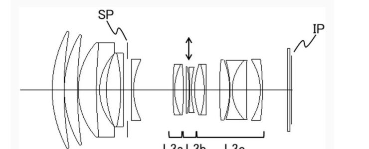
Canon patent application 2023125584 (Japan, published 9/7/2023) discusses optical formulas for three zoom lenses:

  • 200-800mm F5.6-9
  • 100-600mm F5.6-9
  • 20-150mm F4-8

From the patent literature:

A zoom lens is provided that is compact and lightweight and capable of suppressing variations in optical performance over the entire zoom range.

BACKGROUND ART

As an imaging optical system used in an imaging device, there is a demand for a small and lightweight zoom lens that has a high zoom ratio (variable magnification ratio) and high optical performance over the entire zoom range. As a zoom lens that satisfies this requirement, a positive lead type zoom lens in which a lens group with a positive refractive power is arranged closest to the object side is known.

In the zoom lens disclosed in Patent Document 1, the negative second lens group as the main variable magnification group is moved toward the image side during zooming from the wide-angle end to the telephoto end. In order to obtain a higher zoom ratio with this zoom lens, it is necessary to increase the overall length of the lens in order to ensure the amount of movement of the second lens group. As the total length increases, the diameter of the first lens group increases, which is not preferable from the viewpoint of miniaturization and weight reduction.

The present invention provides a zoom lens that is small and lightweight and capable of suppressing fluctuations in optical performance over the entire zoom range, and an imaging device having the same.

Example 1

  • Focal length: 206.00-775.96
  • F-value: 5.83-9.20
  • Half angle of view: 6.00-1.60
  • Image height: 21.64
  • Total length: 330.07-392.54
  • Back focus: 38.46

Example 2

  • Focal length: 100.02-599.98
  • F-value: 5.83-9.20
  • Half angle of view: 12.21-2.07
  • Image height: 21.64
  • Total length: 300.08-373.49
  • Back focus: 77.78

Example 3

  • Focal length: 19.99-150.00
  • F value: 4.12-8.12
  • Half angle of view: 30.77-5.20
  • Image height: 11.90-13.66
  • Total length: 118.37-150.69
  • Back focus: 10.01

More Canon patents are listed here.

[via asobinet]