Canon Patent: 20-120mm F4 And 18-100mm F4 For RF-S Mount
A new Canon patent application (well, not really new) for two lenses for the RF-S mount.
Canon patent application 2023182926 (Japan, published 2023-12-27) discusses optical formulas for two RF-S mount lenses:
- 20-120mm F4
- 18-100mm F4
From the patent literature:
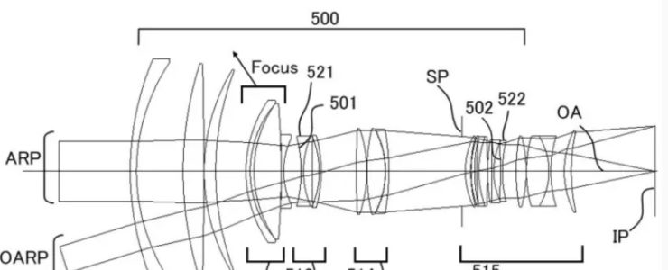
- An object of the present invention is to provide a fixed-length zoom lens having a high zoom magnification and high optical performance over the entire zoom range.
- BACKGROUND ART
Fixed-length zoom lenses are known in which the overall length of the lens does not change during zooming. Such a zoom lens is suitable for video shooting and the like because the center of gravity does not change much during zooming. In recent years, zoom lenses have been required to have high zoom magnification and high optical performance over the entire zoom range for video applications. - However, although the zoom lens described in Patent Document 1 is superior in that there are fewer lens groups that move during zooming and focusing, improvements in optical performance are required as the resolution of sensors has increased in recent years
- On the other hand, in the zoom lens described in Patent Document 2, high optical performance is obtained over the entire zoom range by increasing the number of lenses in each lens group, but an even higher zoom magnification is required.
- The present invention provides a full-length fixed zoom lens having a high zoom magnification and high optical performance over the entire zoom range.
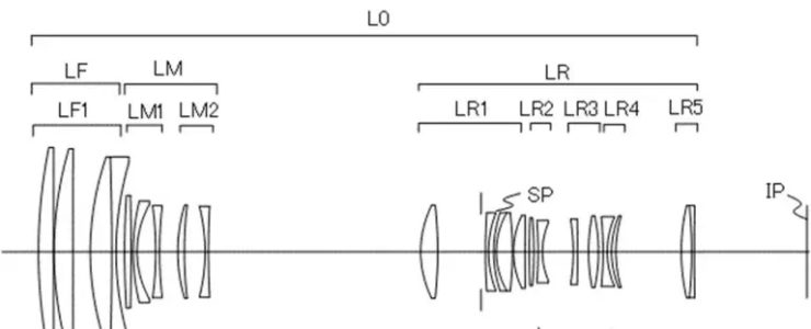
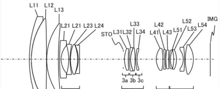
Example 1
- Focal length: 20.02-119.95
- F value: 4.08
- Half angle of view: 34.40-6.31
- Image height: 12.33-13.66
- Total length: 165.00
- Back focus: 13.54
Example 2
- Focal length: 20.01-134.95
- F value: 4.08
- Half angle of view: 34.29-5.61
- Image height: 12.33-13.66
- Total length: 168.51-168.50
- Back focus: 13.82
Example 3
- Focal length: 18.41-101.96
- F value: 4.08
- Half angle of view: 36.59-7.42
- Image height: 12.33-13.66
- Total length: 146.50146.49
- Back focus: 13.77
[via asobinet]