Thanks Barry for the tip.
Is this Canon patent application describing a mirrorless system camera with an EVF and IBIS? We tend to believe it does.
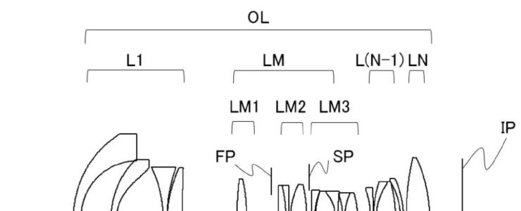
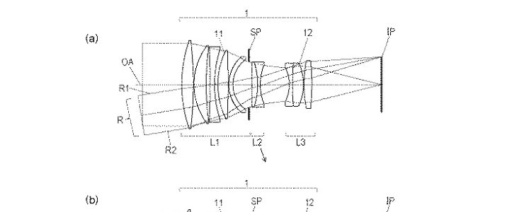
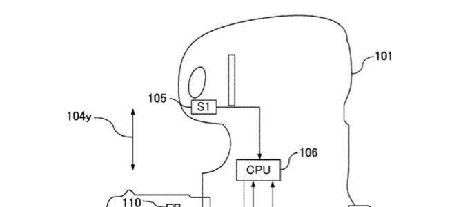
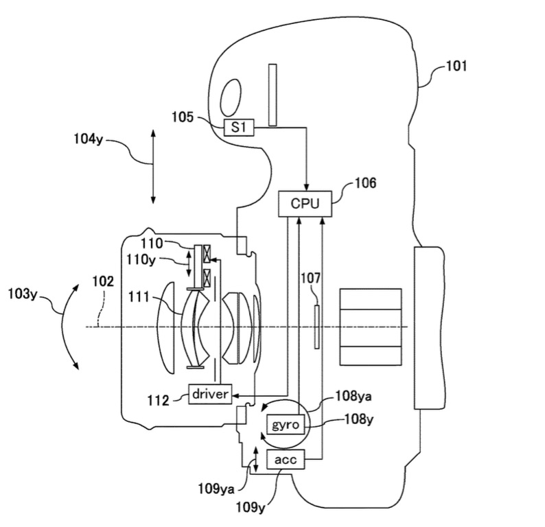
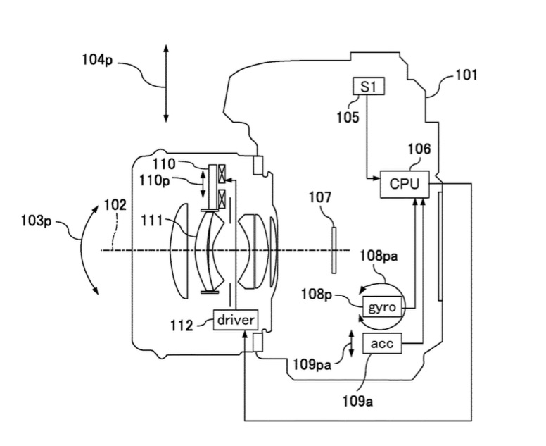
Canon patent application US20180041705 refers clearly to image stabilisation “in camera”. Moreover, as one reader noted, it looks like it will use a current Canon mount, since it doesn’t have the short flange a mirrorless must would have. Furthermore, there is no mirror in the images. It appears that an electronic viewfinder is placed where usually the pentaprism is located.
The patent application abstract says:
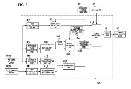
An image shake correcting apparatus in which a first calculating unit calculates a correction coefficient using information corresponding to an angular velocity from a first shake detecting unit and information corresponding to an acceleration output from a second shake detecting unit. A second calculating unit calculates a translational shake correction amount using the correction coefficient and the information corresponding to the angular velocity from the first shake detecting unit. A control unit controls (i) a shake correcting unit that corrects a translational shake according to a third calculating unit that calculates an imaging magnification of an imaging optical system, (ii) a filter selecting a frequency band in which the translational shake correction is performed, and (iii) the translational shake correction amount in the translational shake correction frequency range selected by the filter.
This part of the patent literature makes me think it’s In Body Image Stabilisation (IBIS) technology that’s described:
With respect to a camera incorporating an image shake correcting apparatus, in order to enable photography without image shake, angular shake of the camera due to hand movement, or the like, is detected, and an image shake correcting lens (hereafter “correcting lens”) is driven in accordance with detection values. In this process, it is necessary to accurately detect camera shake and to correct changes in the optical axis due to shaking. Image shake is suppressed by a vibration detecting unit (angular velocity meter, or the like) that obtains detection results, such as angular velocity, and a drive control unit that drives a correcting member (correcting lens, or the like) based on calculating processing results.
Incidentally, in the case of close range photography (an imaging condition of high imaging magnification), there is shake that cannot be detected by an angular velocity meter alone. This is so-called translational shake that is applied in a direction parallel to or vertical to the optical axis of the camera, and image degradation caused thereby cannot be ignored. For example, under conditions when imaging is performed by approaching to within 20 cm of the subject in macrophotography, or when the focal distance of the imaging optical system is extremely large (e.g., 400 mm) relative to a subject that is at a distance of 1 m from the camera, it is necessary to actively detect translational shake and to perform correction.
Any help with patents is always appreciated.