Canon working on weather sealed lens adapter, patent application suggests
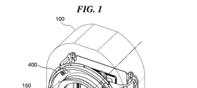
A few days ago we learned how well the EOS 5D Mark IV can cope with water. It’s just natural we found a Canon patent application for what appears to be a weather sealed lens adapter (EF/EF-S to EF-M, is my guess).
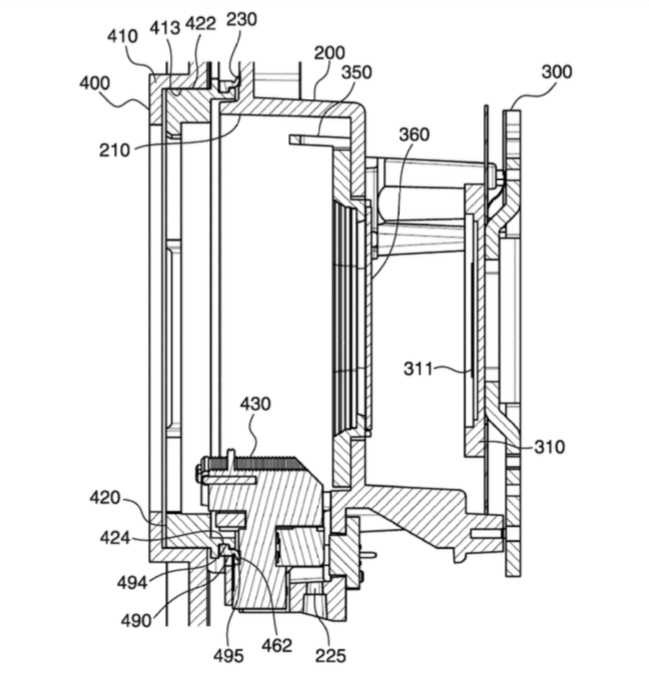
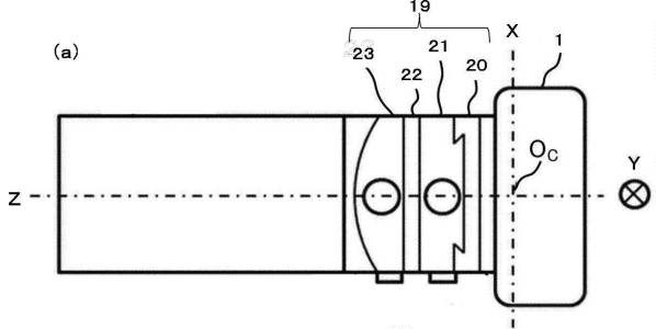
Canon patent application EP20170178735 describes a lens adapter which is protected against dust, water, whatever.
The present invention provides a technique that ensures reliability of an electric connection between a lens adapter and an apparatus body with a simple configuration even when a spacer is inserted between the lens adapter that has an electrical communication unit and the apparatus body of an image pickup apparatus. Moreover, the present invention provides a technique that ensures a dustproof performance between the lens adapter and the apparatus body of the mage pickup apparatus even when the lens adapter has the electrical communication unit.
According to the present invention, the reliability of the electric connection between the lens adapter and the apparatus body is ensured with the simple configuration even when the spacer is inserted between the lens adapter that has the electrical communication unit and the apparatus body of the image pickup apparatus. Moreover, according to the present invention, the dustproof performance between the lens adapter and the apparatus body of the mage pickup apparatus is ensured even when the lens adapter has the electrical communication unit.
I’d love to know what exactly this lens adapter is for. Is it the next iteration of the already existing EF/EF-S to EF-M adapter (![]() ), or has it something to do with Canon’s upcoming full frame mirrorless camera which is rumored since a while? Any help is welcome, patent literature is difficult to read.
), or has it something to do with Canon’s upcoming full frame mirrorless camera which is rumored since a while? Any help is welcome, patent literature is difficult to read.
 Patent applications filed by a company do not necessarily mean the described technology will hit the market any time soon. Patents are a way companies have to protect their intellectual property and research. Some Canon patent applications that in our opinion might indeed go into production are these:
- Patent application describing how to improve burst rate by compressing raw files
- Patent application describing a new way to review photos from a sequential shot
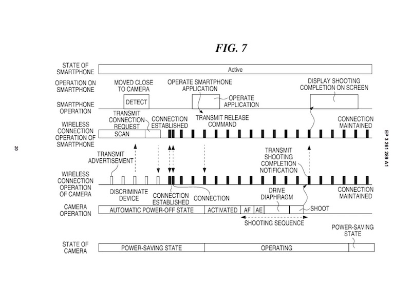
- Patent application that describes technology to improve wireless communication while reducing power consumption
- Patent application to spot and reduce moire artefacts in image data
 Since a few weeks it seems anyone is flooding the web with