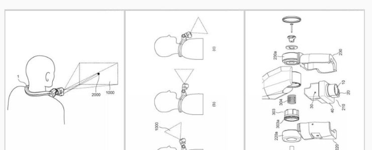
Here is an interesting Canon patent application: a wearable camera that automatically checks and adjusts the shooting position.
Canon patent application 2023152657 (Japan, published 10/17/2023) discusses methods and technology for a wearable camera that can recognize the scene to the degree to automatically adjust the framing of the picture (if I got it right).
From the patent literature:
An object of the present invention is to provide a wearable camera whose imaging direction can be adjusted by a user and whose imaging position can be easily specified.
BACKGROUND ART Wearable cameras have attracted attention in recent years. Various types of wearable cameras are known, such as glasses, neck type, wristwatch, and ring type.
Applications of wearable cameras include, for example, equipment maintenance and remote work support at manufacturing sites. A worker wearing a wearable camera can broadcast video and audio from the site in real time to a remote supporter, and the supporter can give instructions and information to the worker based on the video.
However, since the wearable camera described in Patent Document 1 is worn around the user’s neck, it is difficult for the user to specify the shooting position. In particular, when the angle of the lens is adjusted, it is considered difficult to specify the photographing position after the adjustment.
The present invention has been made in view of the above points, and an object of the present invention is to provide a wearable camera in which the user can adjust the imaging direction, and in which the shooting position can be easily specified. .
Means for Solving the Problems The wearable camera of the present invention includes an imaging section, a fixed section worn by a user, and an irradiation section that irradiates light substantially parallel to the optical axis of the imaging section. A movable part that is movable with respect to the fixed part is provided, and the imaging part and the irradiation part are arranged in the movable part.
The Canon patent application, published on October 18, 2023, discusses methods and technology to make sure autofocus is kept during tilt-shift operations with the lens.
From the patent literature:
An object of the present invention is to provide a control device that can maintain focus with high accuracy even when obtaining a tilt effect or a shift effect.
Background Art Conventionally, a tilt effect that tilts the focusing surface and a shift effect that moves the shooting range have been used to achieve good overall focus on an object surface that is tilted with respect to the optical axis of an imaging optical system. A resulting optical system has been proposed. Patent Document 1 discloses an optical system that can obtain a tilt effect and a shift effect by moving two optical elements in a direction perpendicular to the optical axis.
However, the optical system of Patent Document 1 does not take into account that the amount of defocus changes by moving the optical element in the direction perpendicular to the optical axis, so it does not take into account that the tilt effect or shift effect is applied after focusing. If the optical element is moved in a direction perpendicular to the optical axis in order to obtain an image, the focus will shift.
An object of the present invention is to provide a control device that can maintain focus with high precision even when obtaining a tilt effect or a shift effect.
A new Canon patent application for relatively fast prime lenses.
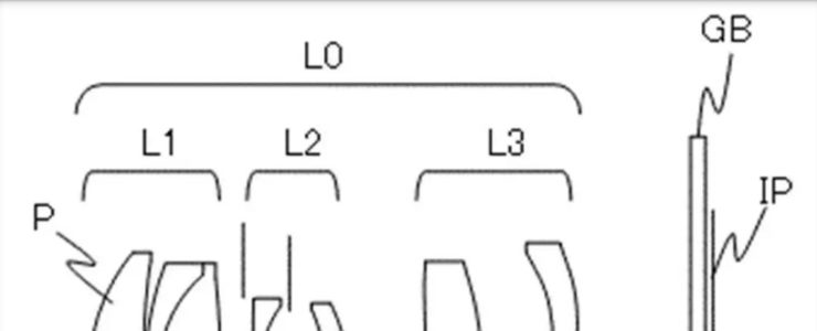
Canon patent application 2023149130 (Japan, published 10/12/2023) discusses optical formulas for prime lenses for the RF mount:
RF 70mm F2
RF 70mm F2.8
RF 75mm F2.4
RF 85mm F2.8
From the patent literature:
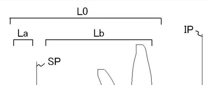
The present invention provides an optical system that is small and lightweight, yet can satisfactorily correct various aberrations including chromatic aberration and obtain high optical performance, and an imaging device having the same.
BACKGROUND ART In recent years, there has been a strong demand for optical systems used in imaging devices to have a compact overall lens system and high optical performance including chromatic aberration correction.
Generally, in a telephoto type optical system, as the focal length becomes longer, the entire lens system becomes larger and its mass increases. In order to miniaturize the optical system with a telephoto power arrangement, it is effective to strengthen the positive refractive power on the object side and the negative refractive power on the image side, but it is effective to increase the positive refractive power on the object side and the negative refractive power on the image side. Challenges arise in balancing both work and life.
Furthermore, in an optical system compatible with a large image sensor, it is important to perform focusing quickly using a small and lightweight lens group, and with less burden on the driving device. In a telephoto optical system, in order to easily perform focusing and to reduce aberration fluctuations during focusing, it is important to appropriately set the lens configuration of each lens group.
Patent Document 1 discloses that a first lens group with positive refractive power, a second lens group with negative refractive power, and a third lens group are arranged in order from the object side to the image side. An optical system is disclosed in which the distance between matching lens groups is varied.
However, in the optical system described in Patent Document 1, the number of lenses constituting the optical system is large, and the optical system cannot be sufficiently miniaturized.
The present invention provides an optical system that is small and lightweight, yet can satisfactorily correct various aberrations including chromatic aberration and obtain high optical performance, and an imaging device having the same.
A new Canon patent application: haptic feedback, i.e. vibration, for feedbacks when “beeps” should be avoided.
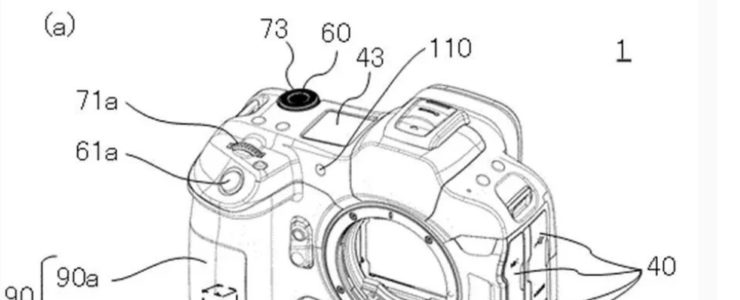
Canon patent application 2023-147064A (Japan, published 10/12/2023) discusses technology and methods to implement a haptic feedback in a camera body.
From the patent literature:
The present invention provides an electronic device that can provide appropriate notification depending on a user’s holding state of the electronic device or a setting state of the electronic device.
BACKGROUND ART: Hitherto, there has been known an electronic device having a function of causing the vibrating device to generate vibration at a predetermined timing and notifying the user. By using vibration (tactile sensation), notifications can be made without relying on sight or hearing, which is useful in that it does not easily affect the user’s operation of electronic devices. Patent Document 1 discloses a configuration in which a plurality of piezoelectric members are arranged in a grip section or a display section of a camera, and the piezoelectric member with the largest contact area with the user’s hand is deformed to notify the user.
However, in the configuration disclosed in Patent Document 1, since the piezoelectric member that has a large contact area with the user’s hand is deformed, depending on the state or setting of the camera, the Users may not be able to properly recognize notifications.
SUMMARY OF THE INVENTION: Therefore, an object of the present invention is to provide an electronic device that can provide appropriate notification depending on the state in which the electronic device is held by the user or the setting state of the electronic device.
It seems the described system recognises how the user is holding the camera body (which hand?) and then activates the right motors, which are the items 100 and 100b in the image on top. If I got it right, the described technology gets the hand position through pressure measurements on the grip. Not sure if this patent will go into production any time soon.
A new Canon patent for a wide-angle single focus lens for a camera with an 1 inch imaging sensor. A new PowerShot camera?
Canon patent application 2023-140823 (Japan, published 10/5/2023) discusses optical formulas for a 28mm-35mm equivalent wide angle lens for a camera with an 1 inch imaging sensor.
From the patent literature:
Optical system and imaging device having the same
The present invention provides an optical system that is compact and has high optical performance, and an imaging device that includes the same.
BACKGROUND OF THE INVENTION
In recent years, with the miniaturization and increase in the number of pixels of image pickup devices, optical systems used in image pickup devices are required to be small and have high optical performance.
Problems to be Solved by the Invention
The optical system described in Patent Document 1 uses a telephoto type power arrangement to reduce the overall length, and uses a plurality of aspheric lenses to reduce distortion and image plane. Curvature is being corrected. However, in the optical system described in Patent Document 1, the Petzval sum of the entire system is large and the incident angle of the off-axis light beam is also large, so when trying to apply it to an imaging device with a large imaging element, it is difficult to correct field curvature or reduce the amount of peripheral light. Decrease is an issue.
Here is another Canon patent for electric tilt-shift lens operation. The other one was published last week.
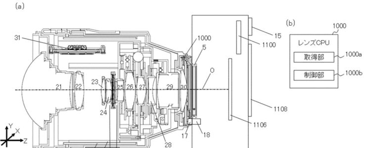
Canon patent application 2023-140195A (Japan, published 10/4/2023) discusses technology and methods for a tilt-shift lens with electronic controls.
From the patent literature:
An object of the present invention is to provide a control device that can establish a desired focus plane for a desired subject or object plane using a desired tilt effect in hand-held photography.
BACKGROUND ART
Conventionally, an optical system has been proposed that has a tilt effect that tilts a focusing surface so that an object surface tilted with respect to the optical axis of an imaging optical system is brought into good focus over the entire surface. . Patent Document 1 discloses a surveillance camera system that includes a lens unit and a camera device that have a tilt effect, determines the amount of tilt for each specific area set as a shooting range, and focuses on a subject using a desired focus plane.
However , in the camera system disclosed in Patent Document 1, when the position of the camera device changes, it is necessary to set the tilt amount for each specific area. Therefore, when hand-held photography is performed using the camera system of Patent Document 1, there is a possibility that the desired tilt effect may not be obtained.
SUMMARY OF THE INVENTION
An object of the present invention is to provide a control device that can establish a desired focus plane for a desired subject or object plane using a desired tilt effect during hand-held photography .
Means for Solving the Problems
A control device as one aspect of the present invention includes an imaging device including an imaging device, and at least one optical member for tilting a focusing surface with respect to an imaging surface of the imaging device. A control device used in a camera system having a lens device having an optical system including an acquisition unit that acquires information about a designated subject, and a subject for constructing a focus plane based on information about the designated subject. and a control unit that acquires information regarding the position of the.
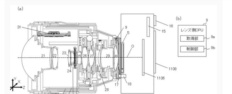
The lens barrel 2 has an optical system, a zoom operation ring 6, a guide barrel 7, a cam barrel 8, a lens-side CPU 9, and an aperture mechanism 11 . The optical system includes a first group lens 21, a second group lens 22, a third group lens 23, a fourth group lens 24, a fifth group lens 25, a sixth group lens 26, a seventh group lens 27, an eighth group lens 28, a ninth group lens 29, and A 10-group lens 30 is provided. In this embodiment, by moving at least one lens (optical member) included in the optical system, at least a tilt effect that tilts the focus plane with respect to the imaging surface of the image sensor 1106 and a shift effect that moves the imaging range are achieved. You can get one. Each lens is held by a lens barrel with a cam follower. The cam follower engages with a straight groove parallel to the optical axis O provided on the guide tube 7 and a cam groove inclined with respect to the optical axis O provided on the cam tube 8. When the zoom operation ring 6 rotates, the cam cylinder 8 rotates, and the positional relationship of each lens in the Z-axis direction changes. As a result, the focal length of the lens barrel 2 changes. The focal length of the lens barrel 2 can be detected by a zoom position detection section (not shown) that detects the amount of rotation of the zoom operation ring 6. The lens-side CPU 009 changes the aperture diameter of the optical system by controlling the aperture mechanism 11. In this embodiment, by moving the sixth group lens 26 and the eighth group lens 28 in a direction perpendicular to the optical axis O, a tilt effect or a shift effect can be obtained. Specifically, by moving the sixth group lens 26 and the eighth group lens 28 in opposite directions, a tilt effect can be obtained, and by moving them in the same direction, a shift effect can be obtained. The lens-side CPU 9 controls the sixth lens group 26 via a drive section using a signal from a detection section (not shown) that detects the amount of movement of the sixth lens group 26 . Further, the lens side CPU 9 controls the 8th group lens 28 via a drive section using a signal from a detection section (not shown) that detects the amount of movement of the 8th group lens 28. The drive unit that moves the sixth group lens 26 and the eighth group lens 28 is, for example, a stepping motor or a voice coil motor (VCM). Note that it is also possible to obtain a tilt effect by tilting (rotating) the lens.
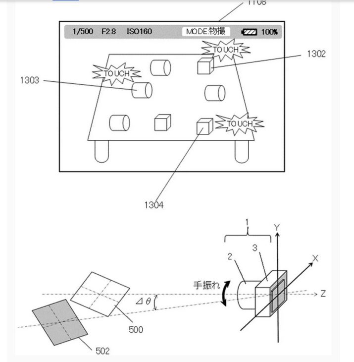
In the camera system 1 of this embodiment, if three points to be focused are specified, the subject plane 500 is constructed as described above, and photography can be performed with the desired subject in focus . However, for example, in so-called “reverse tilt photography (miniature photography)” in which cityscapes and people are photographed by blurring the top and bottom of the photograph, the photographer may decide where to focus and what to blur. In that case, the vector OB is defined by the spatial coordinate points O and B designated by the photographer. The photographer instructs the surface 501 to rotate by an angle θctrl using the vector OB as the rotation axis. For example, the photographer can instruct the surface 501 to rotate by an angle θctrl by performing a touch operation of sliding a finger back and forth on the display unit 1108. Further, instructions may be given using line-of-sight input using the EVF, rotating operation of the aperture operation ring 20, and buttons or dials (not shown). Alternatively, it may be determined automatically according to the set shooting mode of the camera 3. The photographer aligns the object surface 500 with the surface 501 that provides the desired degree of blur while maintaining the desired object (spatial coordinate points O, B) in focus.
This website or its third-party tools use cookies, which are necessary to its functioning and required to achieve the purposes illustrated in the cookie policy. If you want to know more or withdraw your consent to all or some of the cookies, please refer to the cookie policy. By closing this banner you agree to the use of cookies.