Canon Patent: Compact APS-C Wide Primes — 10mm, 12mm, 18mm & 28mm F2.8
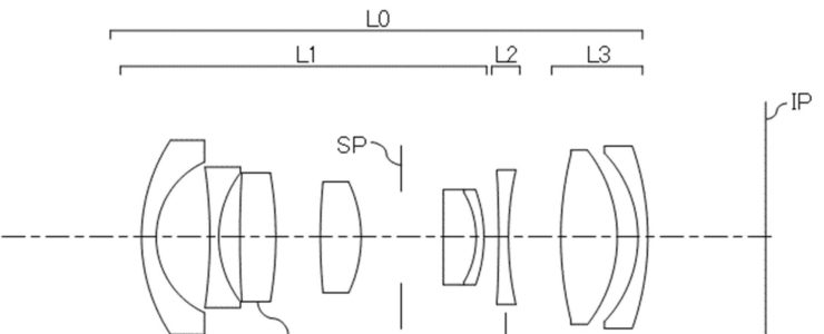
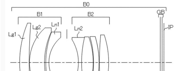
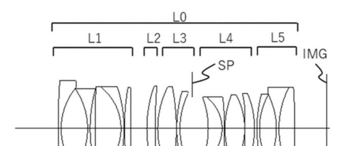
Canon has filed a patent application (publication number P2026052804, published March 25, 2026, filed September 12, 2024) covering optical systems that look suspiciously like a lineup of compact APS-C prime lenses. The patent — titled simply "Optical System and Imaging Device" — presents multiple embodiments clustered around an F/2.8 aperture class, covering focal lengths from 10mm to 28mm.

Here's what the optical data tells us:

Embodiment 1 — ~12mm F2.8

  • Focal length: 12.38mm
  • F-number: 2.83
  • Half angle of view: 42.99°
  • Image height: 11.54mm
  • Total length: 63.50mm
  • Back focus: 12.00mm

Embodiment 3 — ~28mm F2.8

  • Focal length: 28.17mm
  • F-number: 2.83
  • Half angle of view: 24.14°
  • Image height: 12.63mm
  • Total length: 67.03mm
  • Back focus: 15.32mm

Embodiment 4 — ~10mm F2.8

  • Focal length: 10.02mm
  • F-number: 2.83
  • Half angle of view: 48.98°
  • Image height: 11.52mm
  • Total length: 65.00mm
  • Back focus: 12.00mm

Embodiment 7 — ~14mm F2.8

  • Focal length: 14.63mm
  • F-number: 2.83
  • Half angle of view: 39.45°
  • Image height: 12.04mm
  • Total length: 64.29mm
  • Back focus: 16.54mm

Embodiment 8 — ~18mm F2.8

  • Focal length: 18.13mm
  • F-number: 2.83
  • Half angle of view: 33.83°
  • Image height: 12.15mm
  • Total length: 70.71mm
  • Back focus: 12.17mm

What's Canon Up To?

A few things stand out immediately. All embodiments share a tight F/2.83 aperture — clearly a unified F2.8 optical design philosophy across the series. The total lengths are remarkably compact: sub-70mm for everything from 10mm to 28mm is impressive. These aren't the kind of chunky pro primes Canon builds for RF full-frame.

The image heights are the interesting wrinkle. At 11–12mm image height, these designs fall short of what you'd normally expect for APS-C (which typically needs ~14mm image height). Asobinet's own analysis notes this discrepancy, suggesting Canon may be designing these with some built-in cropping in mind — trading a bit of the corner image circle to correct residual distortion in-camera. This isn't unusual; several existing Canon lenses do exactly this.

The back focus situation: With back focus values of 12–15mm across the lineup, these are clearly designed for a short flange-to-sensor distance mount. That points firmly at EF-M or RF-S / EOS R APS-C territory. Canon's EF-M system is effectively on life support at this point, so RF-S is the logical destination — meaning these could be affordable compact primes for the EOS R50 / R10 / R100 crowd.

Does This Mean Anything?

As always with Canon patents: file with healthy skepticism. Canon patents prolifically, and the vast majority never leave the lab. That said, this is a coherent, well-structured lineup — five focal lengths with unified aperture and compact dimensions — which suggests someone at Canon was seriously thinking about a kit of compact APS-C primes. Whether that becomes RF-S 10mm F2.8, 12mm F2.8, 18mm F2.8, and 28mm F2.8 lenses is another question entirely.

What Canon has shown with the RF-S line so far is a willingness to offer affordable, small lenses for their crop-sensor mirrorless bodies. A set of fast-ish primes in this style would fill a real gap in the RF-S lineup, which currently leans heavily on zooms. Fingers crossed this one actually makes it to production.


Source: Asobinet (Japanese) — Patent P2026052804
Canon Patent: Fast Wide Primes — 14mm f/1.4, 18mm f/1.4, 35mm f/1.8 Optical Systems

canon patent

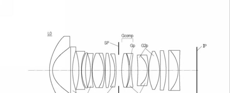
Canon is apparently not done dreaming about fast wide primes. A new patent application published March 12, 2026 (JP P2026043301, filed August 28, 2024) covers a family of large-aperture wide-angle optical systems — and the specs on paper are the kind of thing that makes lens nerds sit up straight.

The stated goal? “Provide an optical system with a large aperture ratio, high optical performance, and fast focusing capability.” Bold words. Let’s look at what they’re actually proposing.

The Patent: Five Optical Systems, One Ambitious Brief

The application includes at least five worked examples spanning a broad range of focal lengths:

ExampleFocal LengthF-valueHalf-angleImage HeightTotal LengthBack Focus
Ex. 114.42mmf/1.4652.34°18.68mm118.50mm14.00mm
Ex. 220.60mmf/1.4642.54°18.90mm117.50mm18.44mm
Ex. 324.72mmf/1.4637.40°18.90mm117.50mm15.00mm
Ex. 418.45mmf/1.4645.46°18.75mm121.17mm17.78mm
Ex. 734.00mmf/1.8530.41°19.96mm98.50mm14.00mm

In plain English: Canon is exploring 14mm f/1.4, 18mm f/1.4, 20mm f/1.4, 24mm f/1.4, and 35mm f/1.8 optical designs — all with large image circles consistent with full-frame sensors.

The Back Focus Situation (Here We Go Again)

Here’s where it gets interesting — and a little speculative. The RF mount has a flange focal distance of 20mm. Several of these designs have back focus values well below that threshold: 14mm (Ex. 1), 15mm (Ex. 3), 14mm (Ex. 7), and 17.78mm (Ex. 4). Only Example 2 at 18.44mm gets close.

Short back focus in a patent design doesn’t automatically disqualify RF compatibility — there are design tricks (rear floating elements, internal focusing groups) that can shift real-world performance away from the listed patent geometry. But it does raise the familiar question that haunts Canon patent watching: are these RF, EF, or something else entirely? Canon has filed similar wide-aperture designs in the past that turned out to be for cinema lenses or specialized applications rather than consumer RF glass.

That said, the image heights (18.68–19.96mm) are solidly full-frame territory, and the total lengths (98–121mm) are reasonable for fast prime construction.

What It Could Mean for Canon Shooters

Canon’s RF wide-prime lineup still has some gaps. The RF14-35mm f/4L IS USM covers the ultra-wide zoom territory, and the RF15-35mm f/2.8L handles the faster end — but dedicated fast wide primes like a 14mm f/1.4 or 20mm f/1.4 would be genuinely new territory for RF. Sony has the FE 14mm f/1.8 G Master and the FE 20mm f/1.8 G; Nikon has the Z 20mm f/1.8 S. Canon RF shooters interested in astrophotography, architecture, or environmental portraits at wide angles have been waiting.

A 35mm f/1.8 RF, meanwhile, would slot neatly between the existing RF35mm f/1.8 Macro IS STM (budget end) and the RF35mm f/1.4 L VCM (flagship). Whether Canon actually wants to fill that middle ground is another question.

The Standard Caveats Apply

Patents are not products. Canon files dozens of optical system patents that never see production glass. This one is interesting because it covers multiple related focal lengths in a single application, which sometimes signals more serious R&D intent — but it’s still early days. Filed in August 2024, published March 2026, and almost certainly years from a camera store near you, if it ever gets there at all.

Still: a 14mm f/1.4 RF would be something. We’ll be watching.


Source: とるなら (asobinet.com) — Patent JP P2026043301, published 2026-03-12, filed 2024-08-28.

Canon Patent: Electric Tilt-shift Lens Operation (take #2)

canon patent

Here is another Canon patent for electric tilt-shift lens operation. The other one was published last week.

Canon patent application 2023-140195A (Japan, published 10/4/2023) discusses technology and methods for a tilt-shift lens with electronic controls.

From the patent literature:

An object of the present invention is to provide a control device that can establish a desired focus plane for a desired subject or object plane using a desired tilt effect in hand-held photography.

BACKGROUND ART

Conventionally, an optical system has been proposed that has a tilt effect that tilts a focusing surface so that an object surface tilted with respect to the optical axis of an imaging optical system is brought into good focus over the entire surface. . Patent Document 1 discloses a surveillance camera system that includes a lens unit and a camera device that have a tilt effect, determines the amount of tilt for each specific area set as a shooting range, and focuses on a subject using a desired focus plane.

However , in the camera system disclosed in Patent Document 1, when the position of the camera device changes, it is necessary to set the tilt amount for each specific area. Therefore, when hand-held photography is performed using the camera system of Patent Document 1, there is a possibility that the desired tilt effect may not be obtained.

SUMMARY OF THE INVENTION

An object of the present invention is to provide a control device that can establish a desired focus plane for a desired subject or object plane using a desired tilt effect during hand-held photography .

Means for Solving the Problems

A control device as one aspect of the present invention includes an imaging device including an imaging device, and at least one optical member for tilting a focusing surface with respect to an imaging surface of the imaging device. A control device used in a camera system having a lens device having an optical system including an acquisition unit that acquires information about a designated subject, and a subject for constructing a focus plane based on information about the designated subject. and a control unit that acquires information regarding the position of the.

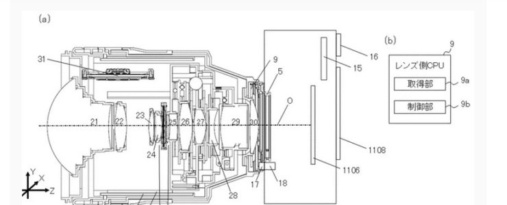
The lens barrel 2 has an optical system, a zoom operation ring 6, a guide barrel 7, a cam barrel 8, a lens-side CPU 9, and an aperture mechanism 11 . The optical system includes a first group lens 21, a second group lens 22, a third group lens 23, a fourth group lens 24, a fifth group lens 25, a sixth group lens 26, a seventh group lens 27, an eighth group lens 28, a ninth group lens 29, and A 10-group lens 30 is provided. In this embodiment, by moving at least one lens (optical member) included in the optical system, at least a tilt effect that tilts the focus plane with respect to the imaging surface of the image sensor 1106 and a shift effect that moves the imaging range are achieved. You can get one. Each lens is held by a lens barrel with a cam follower. The cam follower engages with a straight groove parallel to the optical axis O provided on the guide tube 7 and a cam groove inclined with respect to the optical axis O provided on the cam tube 8. When the zoom operation ring 6 rotates, the cam cylinder 8 rotates, and the positional relationship of each lens in the Z-axis direction changes. As a result, the focal length of the lens barrel 2 changes. The focal length of the lens barrel 2 can be detected by a zoom position detection section (not shown) that detects the amount of rotation of the zoom operation ring 6. The lens-side CPU 009 changes the aperture diameter of the optical system by controlling the aperture mechanism 11. In this embodiment, by moving the sixth group lens 26 and the eighth group lens 28 in a direction perpendicular to the optical axis O, a tilt effect or a shift effect can be obtained. Specifically, by moving the sixth group lens 26 and the eighth group lens 28 in opposite directions, a tilt effect can be obtained, and by moving them in the same direction, a shift effect can be obtained. The lens-side CPU 9 controls the sixth lens group 26 via a drive section using a signal from a detection section (not shown) that detects the amount of movement of the sixth lens group 26 . Further, the lens side CPU 9 controls the 8th group lens 28 via a drive section using a signal from a detection section (not shown) that detects the amount of movement of the 8th group lens 28. The drive unit that moves the sixth group lens 26 and the eighth group lens 28 is, for example, a stepping motor or a voice coil motor (VCM). Note that it is also possible to obtain a tilt effect by tilting (rotating) the lens.

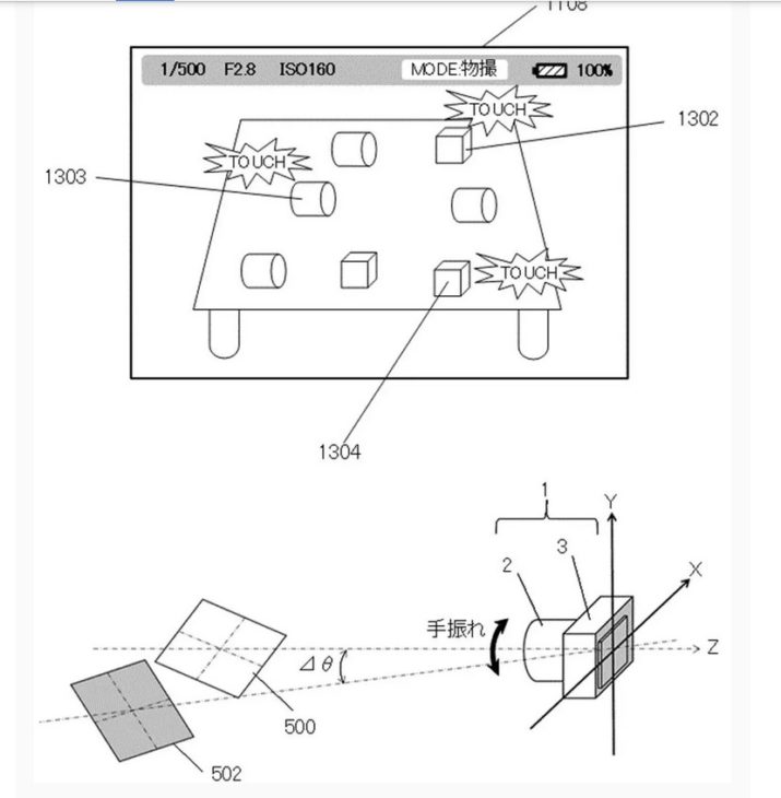
In the camera system 1 of this embodiment, if three points to be focused are specified, the subject plane 500 is constructed as described above, and photography can be performed with the desired subject in focus . However, for example, in so-called “reverse tilt photography (miniature photography)” in which cityscapes and people are photographed by blurring the top and bottom of the photograph, the photographer may decide where to focus and what to blur. In that case, the vector OB is defined by the spatial coordinate points O and B designated by the photographer. The photographer instructs the surface 501 to rotate by an angle θctrl using the vector OB as the rotation axis. For example, the photographer can instruct the surface 501 to rotate by an angle θctrl by performing a touch operation of sliding a finger back and forth on the display unit 1108. Further, instructions may be given using line-of-sight input using the EVF, rotating operation of the aperture operation ring 20, and buttons or dials (not shown). Alternatively, it may be determined automatically according to the set shooting mode of the camera 3. The photographer aligns the object surface 500 with the surface 501 that provides the desired degree of blur while maintaining the desired object (spatial coordinate points O, B) in focus.

More Canon patents are listed here.

[via asobinet]

Canon patent: 55mm F1.24 Lens With Double Gauss Element Arrangement

canon patent

Another Canon patent, although we doubt that this one will ever hit the market.

Canon patent application 2023127280 (Japan, published 9/13/2023) discusses optical formulas for a 55mm F1.24 lens with a double Gauss element arrangement.

From the patent literature:

An object of the present invention is to provide an optical system that has a bright F number, is compact, has high optical performance, and also suppresses fluctuations in various aberrations associated with focusing.

Background Art

In recent years, photographing optical systems with a standard angle of view, where the half angle of view is about 20 degrees to 30 degrees, used in imaging devices have a bright F number and have high optical performance despite the small size of the entire system. That is required. A so-called double Gauss type optical system is known as a standard angle of view photographing optical system. In a Gauss type optical system, the lenses are arranged symmetrically around the aperture, and with a small number of lenses, it is possible to obtain high optical performance despite being compact.

However, in the optical system described in Patent Document 1, the back focus tends to become long and the total length of the lens becomes long, so it is difficult to suppress the increase in size of the imaging device.

In order to achieve a compact lens with a high F-number, high optical performance, and suppression of fluctuations in various aberrations associated with focusing, it is important to appropriately set the structure and material of the lens.

An object of the present invention is to provide an optical system that has a bright F number, is compact, has high optical performance, and also suppresses fluctuations in various aberrations associated with focusing.

Example 1

  • Focal length: 53.80
  • F value: 1.24
  • Half angle of view: 21.91
  • Image height: 21.64
  • Total length: 78.46
  • Back focus: 29.83

Example 2

  • Focal length: 55.98
  • F value: 1.24
  • Half angle of view: 21.13
  • Image height: 21.64
  • Total length: 84.99
  • Back focus: 30.07

Example 3

  • Focal length: 56.00
  • F value: 1.24
  • Half angle of view: 21.12
  • Image height: 21.64
  • Total length: 79.92
  • Back focus: 30.00

More Canon patents are listed here.

[via asobinet]

Canon Patent: In Camera Built-in Neutral Density Filter

Canon patent

That’s an interesting Canon patent that was spotted in japan: a built-in ND (Neutral density) filter.

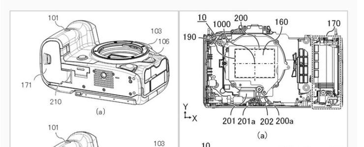
Canon patent application 2023128236 (Japan, published 9/14/2023) discusses methods and technology for an ND filter that is built-in on the camera body.

Excerpts from the patent literature:

An object of the present invention is to provide an imaging device in which an optical filter can be easily switched between a used state and a non-used state, and can appropriately control foreign matter removal from the surface of an imaging unit.

BACKGROUND ART

Conventionally, imaging devices capable of capturing images using optical filters such as neutral density filters (ND filters) have been known. Patent Document 1 discloses an imaging device that includes a plurality of ND filters and can move up and down. Patent Document 2 discloses a configuration including a through hole for blowing gas to blow away dust attached to the ND filter.

In the configuration disclosed in Patent Document 1, it is difficult to hermetically seal the ND filter and the imaging device, so there is a possibility that dust and the like may enter the interior of the imaging device. Although the configuration disclosed in Patent Document 2 can remove dust etc. attached to the ND filter, it is not possible to properly control the function of removing dust etc. attached to the surface of the image sensor unit, so that the captured image may not be affected. Dust, etc. may be reflected.

Therefore, it is an object of the present invention to provide an imaging device in which it is possible to easily switch between a state in which an optical filter is used and a state in which it is not in use, and in which foreign matter removal from the surface of an imaging unit can be properly controlled. purpose.

Effects of the Invention

According to the present invention, an image pickup device in which it is possible to easily switch between the use state and the non-use state of the optical filter, and it is possible to properly control foreign matter removal from the surface of the imaging unit. equipment can be provided.

More Canon patents are listed here.

[via asobinet]

Canon Patent: 24mm F1.4, 35mm F1.4 And 50mm F1.4

canon patent

And yet another Canon patent application. Fast primes for the RF mount.

Canon patent application 2022024113 (japan, published 8/30/2023) discusses optical formulas for three fast prime lenses:

  • 24mm F1.4
  • 35mm F1.4
  • 50mm F1.4

From the patent literature:

Optical system and imaging device

A compact optical system capable of high-speed focusing with a wide angle of view and a large aperture ratio is provided.

Description of the Related Art

Imaging devices using solid-state imaging devices such as CCD sensors and CMOS sensors are required to have optical systems that have a wide angle of view, a large aperture ratio, a small size, and high optical performance. There is also a demand for high-speed autofocus in the optical system.

An optical system with a wide angle of view and a large aperture ratio has the problem that it is difficult to correct various aberrations. In particular, if the weight of the focus lens group is reduced in order to perform high-speed focusing (autofocus), it becomes difficult to suppress aberration fluctuations in focusing from an object at infinity to a close object.

According to the present invention, it is possible to provide a compact optical system capable of high-speed focusing while having a wide angle of view and a large aperture ratio.

Example 1 (24mm F1.4)

  • Focal length 24.36
  • F value 1.44
  • Half angle of view 41.61
  • Image height 21.64
  • Lens length 106.56
  • Back focus 12.72

Example 2 (35mm F1.4)

  • Focal length 34.09
  • F value 1.45
  • Half angle of view 32.40
  • Image height 21.64
  • Lens length 113.84
  • Back focus 13.67

Example 3 (50mm F1.4)

  • Focal length 48.50
  • F value 1.45
  • Half angle of view 24.04
  • Image height 21.64
  • Lens length 108.70
  • Back focus 11.47

More Canon patents are listed here.

[via Digicame Info]