Another Canon patent. An optical formula for a EF 24-105 f/4 lens has been filed by Canon.
The mere fact that Canon (or any other company) makes a patent application for an optical formula (aka lens) does not mean you will see this lens anytime soon. Patents are primarily a way for companies to secure their research. Very few of the many Canon patents you are seeing on the net will ever make it into production.
However, we spend a lot of time to search for patents that might go into production. I think the following patents have a fair chance to be implemented in upcoming Canon cameras:
The patent we are featuring today has a very little chance to go into production in my opinion. However, it’s Canon research so we will feature it. Also, note that there is no image stabilisation in this optical formula.
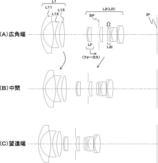
Canon patent US20170374291 describes the optical formula for an EF 24-105 f/4 lens, a classic and widespread focal range for full-frame cameras. Nothing really new. The patent may apply to a lens Canon already made.
The abstract:
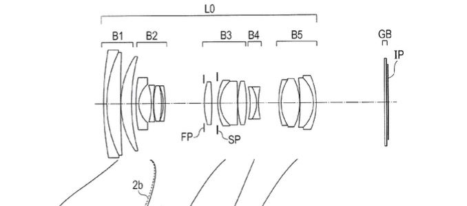
Provided is a zoom lens, including, in order from an object side, a positive first lens unit, a negative second lens unit, a positive third lens unit, a negative fourth lens unit, and a positive fifth lens unit, in which an interval between each pair of adjacent lens units is changed during zooming, in which the second lens unit moves during focusing, and includes, in order from the object side to the image side, a negative lens, a negative lens, a positive lens, and a negative lens, and in which a focal length of the second lens unit, a thickness of the second lens unit on an optical axis, a refractive index of a material of the positive lens included in the second lens unit, and an average value of refractive indices of materials of the negative lenses included in the second lens unit are each appropriately set.
Again, a patent application does not mean that the described technology will go public soon. Patents are in first place a way for companies to secure their research. What they throw to the market is another story.
 Since a few weeks it seems anyone is flooding the web with
 Canon patent application