Canon Patent: Automatic Bracketing For Tilt-shift Lenses

Canon patent

This Canon patent appears to be related to a tilt-shift lens that supports automatic control and allows multiple shots to be taken while automatically setting values. Cool.

Canon patent application 2023179295 (Japan. published 19/12/2023) discusses methods and optical formulas for a what appears to be a fully automated tilt-shift lens.

From the patent literature:

  • An object of the present invention is to easily obtain photographed images with various tilt amounts, shift amounts, and revolving amounts without a user having to make difficult manual adjustments.
  • Background Art
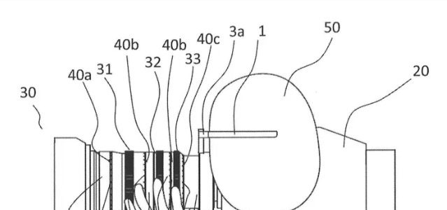
    Focusing can be achieved by tilting the optical system of the optical system with respect to the normal to the imaging surface of the image sensor or by shifting the optical axis parallel to the imaging surface. Lens devices are used that allow photography to be performed by changing the distance range and perspective to suit the subject. Furthermore, there is also a lens device that allows the optical system to rotate (revolving) while being tilted or shifted.
  • Patent Document 1 discloses a lens device that allows a user to tilt or shift an optical system by manually rotating an operation knob.
  • However, in the lens device disclosed in Patent Document 1, the user needs to adjust the tilt amount and shift amount by operating the operation knob while looking through the finder or viewing the live view image displayed on the monitor. be. For users who are not familiar with this operation, it is difficult to adjust the amount of tilt and shift appropriately, and it is also difficult to obtain the desired image because it is difficult to visualize the effect of tilt and shift on the captured image. It is.
  • The present invention provides an imaging device that allows a user to easily obtain captured images with various tilt amounts, shift amounts, and revolving amounts without having to make difficult manual adjustments.
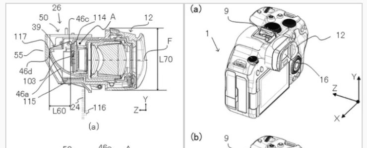
  • An imaging device as one aspect of the present invention performs imaging through an optical system that can be driven by an actuator for at least one movement among tilt, shift, and revolution. The imaging device includes a camera control means that controls an actuator to cause the imaging device to take multiple images while driving the at least one movement by a predetermined amount, and a setting device that allows a user to set a predetermined amount. It is characterized by having the following .
  • A control method as another aspect of the present invention is applied to an imaging device that performs imaging through an optical system that can be driven by an actuator for at least one of tilting, shifting, and rotating movements. The control method includes the steps of: controlling an actuator to cause the imaging device to take multiple images while driving the at least one movement by a predetermined amount; and allowing a user to set the predetermined amount .
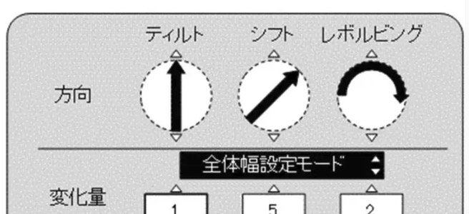
  • Through the above processing, the camera microcomputer 206 determines that at least one of tilting, shifting, and rotating operations on the attached interchangeable lens 100 is possible, and allows the user to make settings regarding bracket photography. In bracket photography, photography is performed a predetermined number of times while changing the drive position of tilt, shift, or revolution by a predetermined amount.
  • The overall width setting mode is a first mode in which the user can set the total driving amount (overall width) of tilting, shifting, or revolving from the start to the end of a series of bracket photography. The overall width is a drive amount that can be set within the entire tilt drive range, the entire shift drive range, and the entire revolving drive range. This overall width setting mode is suitable for finding a setting close to the user’s wishes by performing multiple shootings while roughly changing the drive position of tilt, shift, or revolving.
  • The step width setting mode is a second mode in which the user can set the step width (predetermined amount) of tilt, shift, or revolving to be changed for each photograph. In this step width setting mode, the user has almost found the desired setting, and then takes multiple shots selected by the user while subtly changing the drive position near that setting to finally find the setting that meets the user’s wishes. This mode is suitable for selecting captured images.

More Canon patents are listed here.

[via asobinet]

Canon Patent: Head Mounted Display For Photographic Information

canon patent

A new Canon patent, and I am not sure I understood it entirely.

Canon patent application 2023179231 (Japan, published 12/19/2023) discusses technology and methods for a “head mounted display” that shows photographic information “according to the photographer’s line of sight”. Is this some sort of smart glasses that display information?

From the patent literature:

  • An object of the present invention is to provide a photographing device system having a display member that displays scale information of an operation ring according to the line of sight of a photographer.
  • Conventionally, in order to display photographing information on a head-mounted display device, a system has been proposed in which information is displayed on one of the display sections within the left and right visual fields, as disclosed in Patent Document 1, for example.
  • In the conventional example, an operation on the camera side was required to display information on photographic equipment on the display section. Therefore, when both hands cannot be used for the operation of photographing itself, it is difficult to instantly display the status of necessary parts of the photographic equipment.
  • Accordingly, an object of the present invention is to provide a photographing apparatus system having a display device that is attached to the head and displays the status of necessary photographic equipment according to the photographer’s line of sight.
  • Means for Solving the Problems
    In order to achieve the above object, the present invention provides a lens having a manually operated member and a movable lens group that is driven according to the amount of operation of the manually operated member; It is a head-mounted display device that displays images shot through the lens, and the head-mounted display device includes a display section that divides the display content into left and right sides, and a display section that displays images taken by the head-mounted display device. It has a camera unit that photographs the direction of the person’s line of sight, the manual operation member has a scale marker, and the display unit displays photographing information of the lens at a position near the scale marker. do.
  • Next, a flow for the photographer 50 to obtain photographing information such as the focus, zoom, and iris of the lens 30 during photographing will be described. FIG. 2 shows a state in which the photographer 50 directs his/her line of sight in the direction of the focus ring 31 in order to obtain focus information. The display section 2b on the right eye side of the HMD 1 displays an image captured by the camera 20. One display section 2a is in a state where the surface of the lens 30 is visible through the display section 2a.

Comments welcome :-)

More Canon patents are listed here.

[via asobinet]

Canon Patent: Tilting EVF For Mirrorless Camera

canon patent

Here is a new Canon patent application: a tilting Electronic ViewFinder (EVF) for mirrorless cameras. Rather interesting.

Canon patent application  2023-178037 (Japan, published 12/14/2023) discusses technology and methods for a tiltable EVF to build into a mirrorless camera.

From the patent literature:

  • An object of the present invention is to limit movement and deformation of a flexible substrate in response to movement and rotation of a movable unit.
  • BACKGROUND ART 
    A display unit such as an electronic viewfinder installed in an imaging device can be pulled out from the main body of the imaging device, and can be rotated in the pulled out state, so that the user can take an image. There is something that expands the degree of freedom in posture.
  • Patent Document 1 discloses an imaging device equipped with a finder unit that can be pulled out and rotated. In this imaging device, a flexible board is used for electrical connection between the board provided in the finder unit and the control unit fixed to the main body, and the flexible board changes as the finder unit is pulled out and rotated relative to the main body. transform.
  • However, in the imaging device disclosed
    in Patent Document 1, there are insufficient restrictions on the movement and deformation of the flexible substrate in response to the pull-out and rotation of the finder unit relative to the main body. Therefore, there is a risk that an excessive load will be applied to the flexible substrate or that the flexible substrate will be caught between other members.
  • The present invention provides an electronic device in which excessive load or pinching of the flexible substrate can be avoided by restricting the movement and deformation of the flexible substrate in accordance with the movement and rotation of a movable unit such as a display unit. provide.

More Canon patents are listed here.

[via asobinet.com]

Save 25% On Topaz Photo AI and Video AI (limited time)

photo ai

For the holidays, Topaz Labs started a promotion on their award winning products, Photo AI and Video AI, which are 25% off.

You can get Photo Ai at $149 (reg. $199) and Video AI at $224 (reg. $299) – see here for trial version and more information.

More selected deals:

Canon Patent: 70-150mm f/2 and 70-200mm f/2.8 With Inner Zoom

canon patent

Here is a new Canon patent application, two lenses with inner zoom mechanism.

Canon patent application 2023176289 (Japan, published 12/13/2023) discusses optical formulas and methods for two zoome lenses with a not extending zoom mechanism:

  • 70-150mm f/2
  • 70-200mm f/2.8

From the patent literature:

  • An object of the present invention is to provide a zoom lens that has a long focal length and a large aperture ratio, yet is both compact and lightweight and has high optical performance.
  • BACKGROUND ART
    Zoom lenses used in imaging devices are required to be small and lightweight, to satisfactorily correct various aberrations including chromatic aberration, and to have high optical performance. Furthermore, zoom lenses are required to have a long focal length at the telephoto end, a small F number, and a large aperture ratio. Furthermore, zoom lenses are required to have a large zoom ratio and be easy to manufacture.
  • However, the zoom lens described in Patent Document 1 tends to have large aberrations including chromatic aberration, making it difficult to have high optical performance. If the power of the lens groups making up the zoom lens is weakened in order to better correct the aberrations, the zoom lens will become larger. Furthermore, if aberrations are corrected by increasing the number of lens groups that make up the zoom lens, the mechanical mechanism will become complicated and the zoom lens will become larger.
  • The present invention provides a zoom lens that has a long focal length and a large aperture ratio, yet is both compact and lightweight and has high optical performance.

Example 1

  • Focal length: 72.10-146.49
  • F value: 2.05
  • Half angle of view: 16.70-8.40
  • Image height: 21.64
  • Total length: 217.31
  • Back focus: 13.71

Example 2

  • Focal length: 72.12-194.03
  • F value: 2.90
  • Half angle of view: 16.70-6.36
  • Image height: 21.64
  • Total length: 217.47
  • Back focus: 37.98

Example 3

  • Focal length: 98.00-291.00
  • F value: 2.90
  • Half angle of view: 12.64-4.25
  • Image height: 21.64
  • Total length: 317.42
  • Back focus: 38.00

Example 4

  • Focal length: 101.97-389.88
  • F value: 4.10
  • Half angle of view: 11.98-3.18
  • Image height: 21.64
  • Total length: 359.04
  • Back focus: 52.64

More Canon patents are listed here.

[via asobinet]

Nikon Made A Special Firmware For NASA, To Avoid Cosmic Rays In Photos

nikon z 9

Well, if this is not a nice technological thing by Nikon. Making a special firmware to block cosmic rays in photos.

In an interview with PetaPixel, astronaut Don Pettit talks about the changes that Nikon made to firmware.

Excerpt from the interview:

“Our cameras in space get sensor damage from galactic cosmic rays and after about six months we replace all the cameras but you still have cameras with significant cosmic ray damage,” explains Pettit.

“It shows up at fast shutter speeds, not just the slow ones. So we got Nikon to change the algorithm so that it can do in-camera noise reduction at shutter speeds of up to 500th of a second.”

Pettit says Nikon’s in-camera noise reduction “does wonders” for getting rid of the cosmic ray damage and that “trying to get rid of it after the fact is really difficult.”

NASA used to use Hasselblad cameras, but then started using Nikon cameras. Apparently , there are between 12 and 15 Nikon D5 cameras on the ISS (International Space Station). According to Don Pettit, they are “in the process of switching over to the Z9 and [they are] going to slowly replace the lenses with the Z lenses, initially replacing the lenses that require the mechanical autofocus.