Wireless charging may come to Canon cameras, patent application suggests – Update
UPDATE: sorry folks, turns out we have been fooled. It’s a patent application of 2015, and Canon showed a working prototype at Canon Expo 2015,
Original post:
It appears Canon is working to feature wireless charging on their future cameras. Wireless charging is already a reality on smartphones and similar devices.
The patent literature describes…:
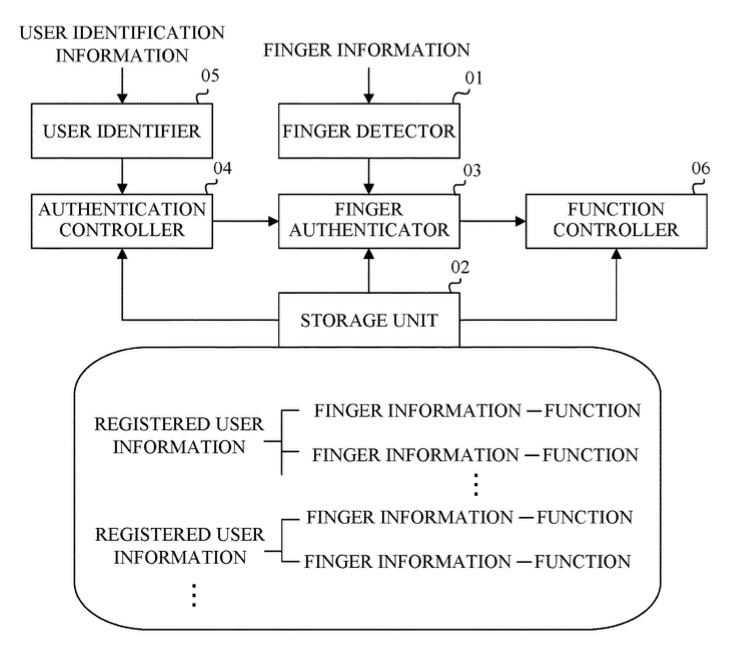
An electronic device comprising: a power receiver that wirelessly receives power from a power supply apparatus; a first communicator; a connection interface that connects a detachable communication device to the electronic device, wherein the detachable communication device includes a second communicator that performs wireless communication; and a CPU that (a) determines whether the detachable communication device that is currently connected is capable of using a wireless power supply from the power supply apparatus, if the detachable communication device and the connection interface are connected, and (b) controls the first communicator to transmit data for notifying the power supply apparatus that the detachable communication device that is currently connected is not capable of using the wireless power supply if the detachable communication device that is currently connected is not capable of using the wireless power supply.
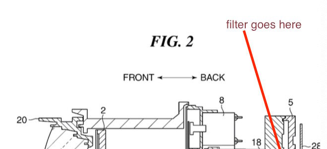
Memory cards used for wireless transmission may interfere with wireless charging, an issue the patent literature takes in account:
Description of the Related Art
In recent years, a wireless power supply system, which includes a power supply apparatus wirelessly outputting power without connection by a connector, and an electronic device charging a battery by the power wirelessly supplied from the power supply apparatus, has been used.
[…]In such a wireless power supply system, the electronic device includes a communication unit which transmits a response to a command transmitted from the power supply apparatus.
In such a wireless power supply system, the power supply apparatus controls power supply to the electronic device in accordance with a response obtained from the communication unit included in the electronic device.
In recent years, a memory card having a function of performing wireless communication has been used. For example, in a case where such a memory card is inserted into an electronic device, even when the power supply apparatus performs wireless communication required for controlling power supply to the electronic device, the memory card may transmit a response is not associated with wireless power supply to the power supply apparatus. In this case, the power supply apparatus may not appropriately control wireless power supply to the electronic device.
Furthermore, since the power supply apparatus performs wireless power supply to the electronic device, a magnetic field generated in an antenna of the power supply apparatus may affect the memory card inserted into the electronic device, and accordingly, the power supply apparatus may not appropriately perform the wireless power supply to the electronic device.
Please note: a patent application doesn’t mean the described technology will go into production any time soon. Patents are primarily a way companies have to protect their research and development.
Some Canon patent applications we think might get into production are these:
- Patent application describing how to improve burst rate by compressing raw files
- Patent application describing a new way to review photos from a sequential shot
- Patent application that describes technology to improve wireless communication while reducing power consumption
- Patent application to spot and reduce moire artefacts in image data
- Patent application for weather sealed lens adapter
 Among the huge amount of patent applications filed by Canon, some show how intensely Canon is researching sensor technology.
 Is there something coming from Canon, something small? After a patent application to
 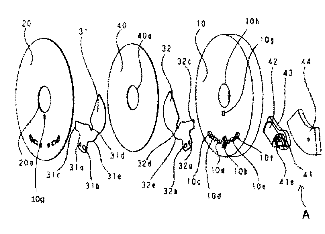 Canon patent application JP-A-2018-10053 describes how to improve the durability of shutter blades.