Canon patent to improve raw file burst rate through lossy compression
 Canon patent application US20170359471 describes an algorithm to improve raw file writing performance during burst shoots. This is an example of patent that likely will be found on a future Canon DSLR.
The patent abstract:
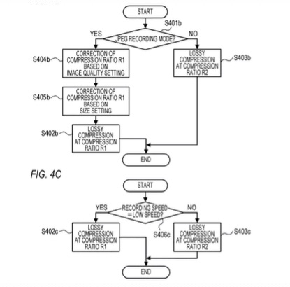
An imaging apparatus according to the present invention includes: an imaging unit configured to generate RAW image data by imaging; a generation unit configured to generate record RAW image data from the RAW image data; and a recording unit configured to record in a storage unit the record RAW image data, wherein the generation unit generates the record RAW image data by performing Lossy compression on the RAW image data in a case where consecutive shooting is performed, and generates the record RAW image data by performing Lossless compression on the RAW image data in a case where single shooting or bracket photographing is performed.
The interesting aspect is: raw files are compressed and saved lossy only when burst shooting, during normal operation raw files will be saved lossless. The patent literature states the algorithm:
- record RAW image data is generated by performing lossy compression on the RAW image data in a case where consecutive shooting is performed, and
- record RAW image data is generated by performing lossless compression on the RAW image data in a case where single shooting or bracket photographing is performed.
I am not sure if I want lossy compressed raw files on my camera. What about you?
 Here is a Canon patent (United States Patent