Canon Patent Application For RF 17-72mm f/3.5-5.8 Lens For EOS R
Here is a Canon patent application for a zoom lens for the Canon EOS R full frame mirrorless system.
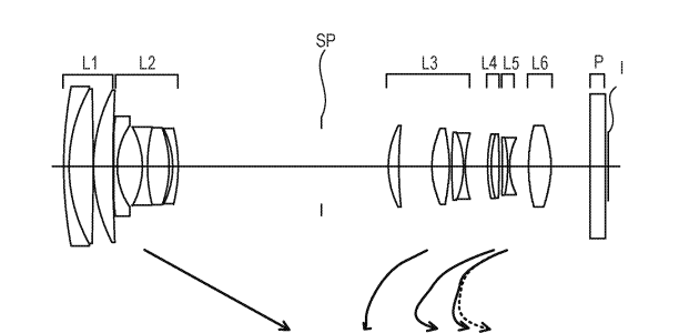
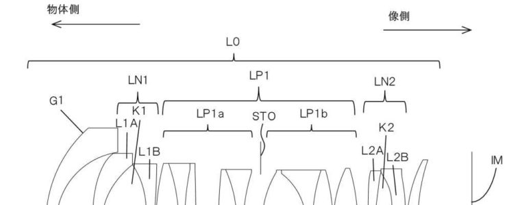
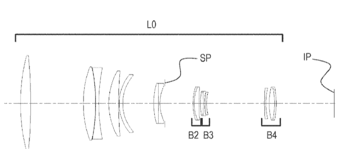
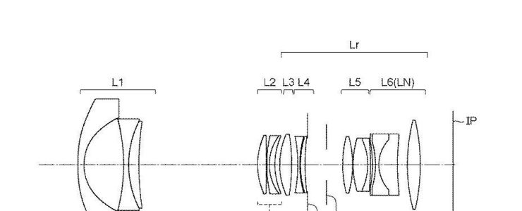
This Canon patent application (2019-211513) discusses the optical formula for an RF 17-72mm f/3.5-5.8 lens.
- Zoom ratio: 4.25
- Focal length: 17.10 34.82 72.70 mm
- F number: 3.57 4.18 5.85
- Half angle of view: 51.68 31.85 16.57
- Image height: 21.64 21.64 21.64 mm
- Lens length: 151.00 135.57 157.71 mm
- Back focus: 13.13 27.81 63.49 mm
More Canon patent applications are listed here. Some particularly interesting patent applications we think might get into production are these:
- A cooling adapter for the RF mount (R5 overheating?)
- A bunch of macro lenses for the RF mount.
- A 8mm f/4 circular fisheye lens for the Canon EOS R system
- A battery grip that works with differently siszed cameras
- A 100-400mm f/5.5-7.1 lens for APS-C cameras. EOS M or DSLR?
- RF 17-70mm lens for EOS R system
- IBIS coming to the EOS M and PowerShot lineup?
- Patent Application: mirrorless camera with large display and virtual control wheel
- Patent Application: IBIS and Lens IS Working Together
- Patent application for high speed mirror movement and control
- Patent application for an RF 14-28mm f/2 lens
- Patent application for an RF 50mm f/1.8 lens
- Patent application for a smart lens cap
- Patent application for celestial auto-focus
- Patent application describing a Pop-Up Flash With LED
- Patent application describing the optical formula for a RF 70-300mm F/4-5.6 IS lens for EOS R systems
- Patent application describing how to improve burst rate by compressing raw files
- Patent application describing a new way to review photos from a sequential shot
- Patent application that describes technology to improve wireless communication while reducing power consumption
- Patent application to spot and reduce moire artefacts in image data
- Patent application for weather sealed lens adapter
- Patent application for AI powered predictive camera control system
- Patent application for 18-55mm kit lens with LCD display
- Patent application to reduce noise in image files