Canon Patent: Medical Devices To Use EOS R Technology
Canon wants their EOS R system (and technology) to be everywhere. Medical devices included.
A newly spotted Canon patent (published 6/6/23) discusses methods and technology to implement EOS R camera technology on medical devices.
From the patent literature:
An object of the present invention is to provide an imaging apparatus that enables confirmation of medical information and imaging parameters, and also allows confirmation of medical information before imaging of image data.
Description of the Related Art Techniques
For associating an image with information about the subject of the image have been proposed. In Patent Document 1, in an imaging device, an image of a code is captured, the code is analyzed, patient information corresponding to the code is acquired from a database, the patient information is superimposed on a live view image, and captured image data is obtained. It is described that patient information is recorded in association with.
In a camera that stores medical information such as patient information in association with image data, it is important for the user to confirm that the medical information is correct. there is Furthermore, at the time of shooting, it is also important to check shooting parameters (Av/Tv/exposure compensation/Iso, etc.) for shooting high-quality image data.
SUMMARY OF THE INVENTION
Accordingly, it is an object of the present invention to provide an imaging apparatus that
enables confirmation of medical information and imaging parameters, and also allows confirmation of medical information prior to imaging of image data.
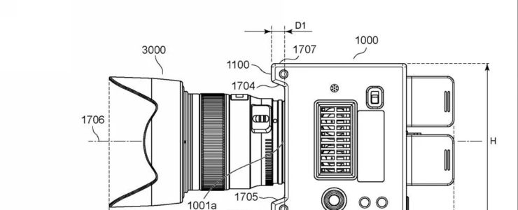
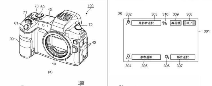
This going to be part of Canon’s Medical Photo Solutions. The example shows a camera with an EOS R-like design and the ability to display medical parameters. Using the network system, it will be possible to display information on the camera by linking it with the hospital system.
[via asobinet]