Canon Patent: 200-400mm F4 x 1.4 & 200-500mm F4 x 1.4 Lenses For RF Mount
A new Canon patent application for two RF-mount telephoto lenses with extender: 200-400mm F4 x 1.4 and 200-500mm F4 x 1.4.
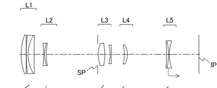
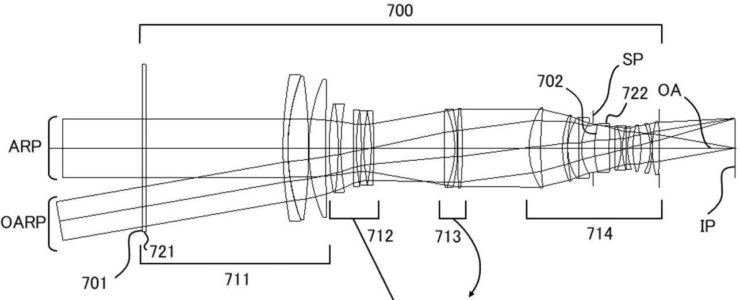
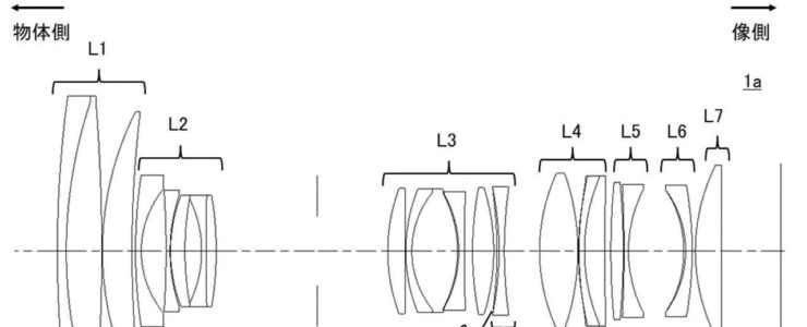
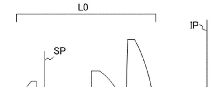
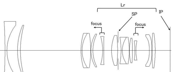
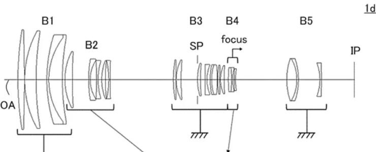
Canon patent application P2022185663 (Japan, published 12/15/2022) discusses optical formulas for two RF-mount telephoto lenses with 1.4 extender, the RF 200-400mm F4 x 1.4 and RF 200-500mm F4 x 1.4.
From the patent literature:
Kind Code: A1 To provide a compact, high-performance zoom lens into which an extender group can be inserted.
BACKGROUND ART
Patent Document 1 and Patent Document 2 disclose an optical system (telephoto lens) in which a magnification conversion optical group (extender group) for extending the focal length on the telephoto end side can be inserted and removed.
In the optical systems disclosed in Patent Documents 1 and 2, an extender is provided on the image side of the stop for the purpose of downsizing. In this case, since it is necessary to secure a wide interval between the lens groups on the image side of the diaphragm, it is necessary to arrange the focus lens group on the object side of the diaphragm. If the focus lens group is arranged on the object side of the diaphragm, the diameter of the focus lens group is determined by the diameter of the Fno light beam at the telephoto end.
SUMMARY OF THE INVENTION
Accordingly, it is an object of the present invention to provide a small-sized, high-performance zoom lens and an imaging device into which an extender group can be inserted.
Example 1
- Focal length: 205.1-385.5
- F-value: 4.1
- Half angle of view: 5.99-3.21
- Image height: 21.635
- Total length: 367.62
- Back focus: 39.994
Example 2
- Focal length: 290.4-543.2
- F-value: 5.8
- Half angle of view: 4.26-2.28
- Image height: 21.635
- Total length: 367.62
- Back focus: 39.994
Example 3
- Focal length: 207.0-487.9
- F-value: 4.1
- Half angle of view: 5.97-2.54
- Image height: 21.635
- Overall length: 410.05
- Back focus: 39.998
Example 4
- Focal Length: 288.1-678.9
- F-value: 5.7
- Half angle of view: 4.30-1.83
- Image height: 21.635
- Overall length: 410.05
- Back focus: 39.998
More Canon patent applications are listed here. Some particularly interesting patent applications we think might get into production are these:
- RF 16-28mm lens with either f/2.8, f/2.8-4, or f/4
- Automatic shutter silencing based on subject and distance
- A bunch of prime lenses for the RF mount
- An improved Electronic Viewfinder
- Patent application for RF 50mm F1.4 and an RF 35mm f/1.4 lenses
- A zoom lens that might be for an EOS R with APS-C sensor
- A smaller IBIS unit.
- A cooling adapter for the RF mount (R5 overheating?)
- A bunch of macro lenses for the RF mount.
- A 8mm f/4 circular fisheye lens for the Canon EOS R system
- A battery grip that works with differently siszed cameras
- A 100-400mm f/5.5-7.1 lens for APS-C cameras. EOS M or DSLR?
- RF 17-70mm lens for EOS R system
- IBIS coming to the EOS M and PowerShot lineup?
- Patent Application: mirrorless camera with large display and virtual control wheel
- Patent Application: IBIS and Lens IS Working Together
- Patent application for high speed mirror movement and control
- Patent application for an RF 14-28mm f/2 lens
- Patent application for an RF 50mm f/1.8 lens
- Patent application for a smart lens cap
- Patent application for celestial auto-focus
- Patent application describing a Pop-Up Flash With LED
- Patent application describing the optical formula for a RF 70-300mm F/4-5.6 IS lens for EOS R systems
- Patent application describing how to improve burst rate by compressing raw files
- Patent application describing a new way to review photos from a sequential shot
- Patent application that describes technology to improve wireless communication while reducing power consumption
- Patent application to spot and reduce moire artefacts in image data
- Patent application for weather sealed lens adapter
- Patent application for AI powered predictive camera control system
- Patent application for 18-55mm kit lens with LCD display
- Patent application to reduce noise in image files
[via asobinet]